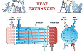
Heat exchanger is used to exchange the heat from one fluid to another. In heat exchangers the temperature of each fluid changes as it passes through the exchanger, and hence the temperature of the dividing wall between the fluids also changes along the length of exchanger. Heat exchangers have many applications in engineering such as air intercoolers and evaporators, condensers and boilers in steam power plant, condensers and evaporators in refrigeration units, etc. In this text, we will discuss about parallel flow heat exchanger, counter flow heat exchange, and cross flow heat exchanger.
7.2.1 Parallel and Counter Flow Heat Exchangers
Consider the case of a fluid flowing through a pipe and exchanging heat with a second fluid flowing through an annulus surrounding the pipe. When the fluids flow in the same direction along the pipe the system is known as parallel flow, and when the fluids flow in opposite directions to each other the system is known as counter flow. Parallel flow is shown in Figure 7.9a, b; and counter flow heat exchanger is shown in Figure 7.9c, d.
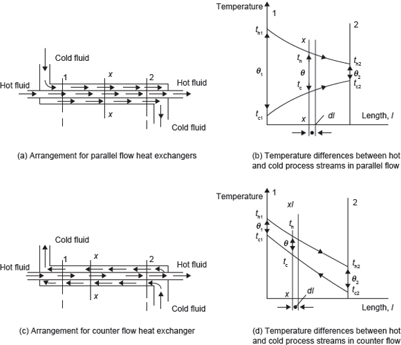
Figure 7.9 Parallel and Counter Flow Heat Exchangers
Let the mean inlet and outlet temperatures of hot fluid be th1 and th2, respectively, and let the mean temperature of cold fluid at sections 1 and 2 be tc1 and tc2, respectively. Let the mass flow rates of hot fluid and cold fluid be m· h and m· c, respectively. The temperature difference at section 1 is (th1 – tc1) = θ1, and temperature difference at section 2 is (th2 – tc2) = θ2.
There is tubular arrangement for parallel and counter flow heat exchangers. Therefore, the electrical analogy for heat transfer from one fluid to another can be given as
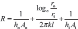
where ho, hi are the heat transfer coefficients for the fluid flow outside the inner tube and inside the inner tube, respectively. ro and ri are the outer and inner radii of inner tube and Ao and Ai are the outer and inner surface area of inner tube.
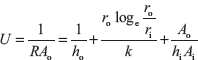
If we define overall the heat transfer coefficient, U as
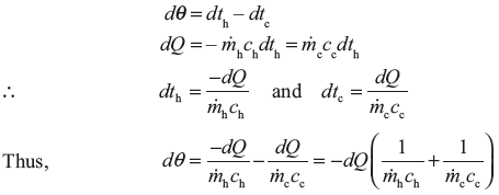
Consider a section X–X, where hot fluid is at th and cold fluid is at tc. The temperature difference at this section is (th – tc) = θ, and a small amount of heat, dQ, is transferred across an element of length dl. Now using the equation, Q = U × A × (th – tc)
dQ = 2π rdlθ (7.1)
where r is mean radius of the tube.
In the case of parallel flow heat exchanger, temperature th decreases with the length l, while temperature tc increases with the length l. The heat given up by hot fluid must be equal to heat received by cold fluid for parallel flow.
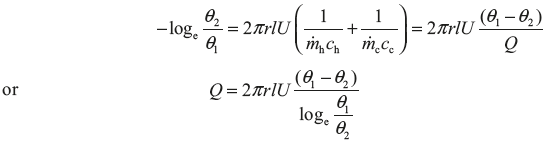
On integrating, we get
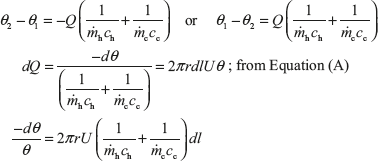
Also, on integrating, we get
In the case of counter flow, both temperatures th and tc decrease in the direction of the length l.
Therefore, 
Similar to the parallel flow, for counter flow we can find 
 is known as logarithmic mean temperature difference (LMTD).
Thus,
Q = UAθm
where
A = 2πrl
Example 7.7: Exhaust gases flowing through a tabular heat exchanger at the rate of 0.25 kg/s are cooled from 360°C to 100°C by water initially at 15°C. The specific heat of exhaust gases and water may be taken as 1.14 and 4.18 kJ/kgK, respectively; the overall heat transfer coefficient from gases to water is 140 W/m2K. Calculate the surface area required when the cooling water is 0.5 kg/s for parallel flow and counter flow.
Solution:
- For parallel flow as shown in Figure 7.10Heat given up by exhaust gas is equal to heat taken up by water. Therefore,
 Figure 7.10 Parallel Flow Heat Exchanger
- For counter flow as shown in Figure 7.11Heat given up by exhaust gas is equal to heat taken up by water. Therefore,
 Figure 7.11 Counter Flow Heat Exchanger
7.2.2 Cross flow Recuperator
A simple cross flow recuperator is shown in Figure 7.12. The calculation of the mean temperature difference is much more difficult in this case. Θm depends on the ratio of the product of the mass flow and specific heat of fluids A and B, as well as on the ratio of the temperature difference between the fluids at inlet and outlet.

Figure 7.12 Cross Flow Recuperator
7.2.3 Multi-pass and Mixed Flow Recuperators
To increase the necessary surface area with a simple tube and annulus arrangement, the length of the tube may be too large for practical purposes. In order to make the heat exchanger more compact, which is desirable from space considerations, and also to reduce the heat loss from the outside surface, it is necessary to have several tubes and perhaps several passes or bundles of tubes. The flow can be either cross flow, or a mixture of parallel flow, counter flow, and cross flow as shown in Figure 7.13. The latter case is called mixed flow.

Figure 7.13 Multi-pass Recuperator
SUMMARY
The chapter can be summarized as follows:
- From the second law of thermodynamics, heat flows whenever there is existence of temperature difference or temperature gradient.
- Heat is a form of energy which is transferred from one body to another body at a lower temperature, by virtue of the temperature difference between the bodies.
- Conduction is the heat transfer from one part of a substance to another part of the same substance, or from one substance to another in physical contact with it, without appreciable displacement of the molecules forming the substance.
- The law of heat transfer in conduction mode at a macroscopic level is based on experiments of Biot and formulated by J.B. Fourier in 1882.
- Convection is the term used for heat transfer mechanism which takes place in a fluid because of a combination of conduction due to the molecular interactions and energy transport due to the macroscopic motion of the fluid itself.
- All matter continuously radiates electromagnetic radiation unless its temperature is absolute zero.
- Heat exchanger is used to exchange the heat from one fluid to another.
- In heat exchangers the temperature of each fluid changes as it passes through the exchanger, and hence the temperature of the dividing wall between the fluids also changes along the length of exchanger.
Leave a Reply