
The closed path in which direct current flows is called d.c. circuit.
A simple d.c. circuit is shown in Figure 1.12 which contains a d.c. source (battery), a load (lamp), a switch, connecting leads and measuring instruments such as ammeter and voltmeter.
The simplified line diagram of the same d.c. circuit is shown in Figure 1.13. The load resistors are connected in series, parallel, or series–parallel combination as per the requirement.
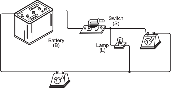
Fig. 1.12 Pictorial view of dc circuit
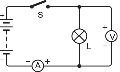
Fig. 1.13 Line diagram of dc circuit with measuring instruments
1.31 SERIES CIRCUITS
In the circuit, a number of resistors are connected end to end so that same current flows through them is called series circuit.
Figure 1.14 shows a simple series circuit. In the circuit, three resistors R1, R2, and R3 are connected in series across a supply voltage of V volt. The same current (I) is flowing through all the three resistors.
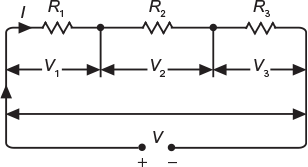
Fig. 1.14 Resistors connected in series
If V1, V2, and V3 are the voltage drops across the three resistors R1, R2, and R3, respectively, then
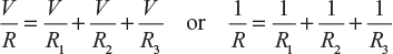
V = V1 + V2 + V3 = IR1 + IR2 + IR3 (Ohm’s law)
Let ‘R’ be the total resistance of the circuit, then
IR = IR1 + IR2 + IR3 or R = R1 + R2 + R3
that is, Total resistance = Sum of the individual resistances.
The common application of this circuit is in the marriages for decoration purposes where a number of low-voltage lamps are connected in series. In this circuit, all the lamps are controlled by a single switch, and they cannot be controlled individually. In domestic, commercial, and industrial wiring system, the main switch and fuses are connected in series to provide the necessary control and protection.
1.32 PARALLEL CIRCUITS
In this circuit, one end of all the resistors is joined to a common point and the other ends are also joined to another common point so that different current flows through them is called parallel circuit.
Figure 1.15 shows a simple parallel circuit. In this circuit, three resistors R1, R2, and R3 are connected in parallel across a supply voltage of V volt. The current flowing through them is I1, I2, and I3, respectively.
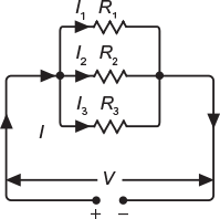
Fig. 1.15 Resistors connected in parallel
The total current drawn by the circuit,
I = I1 + I2 + I3 ![]() (according to Ohm’s law)
(according to Ohm’s law)
Let ‘R’ be the total or effective resistance of the circuit, then
that is, Reciprocal of total resistance = sum of reciprocal of the individual resistances.
All the appliances are operated at the same voltage, and therefore, all of them are connected in parallel. Each one of them can be controlled individually with the help of a separate switch.
1.33 SERIES–PARALLEL CIRCUITS
The circuit in which series and parallel circuits are connected in series is called series–parallel circuit.
Figure 1.16 shows a simple series– parallel circuit. In this circuit, two resistors R1 and R2 are connected in parallel with each other across terminals AB. The other three resistors R3, R4, and R5 are connected in parallel with each other across terminal BC. The two groups of resistors RAB and RBC are connected in series with each other across the supply voltage of V volt.
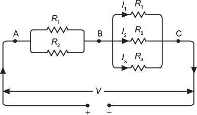
Fig. 1.16 Resistors connected in series-parallel combination
The total or effective resistance of the whole circuit can be determined as given below:
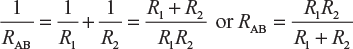
Similarly,
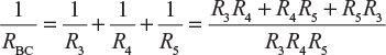
or
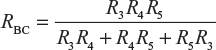
Total or effective resistance of the circuit, R = RAB + RBC
1.34 DIVISION OF CURRENT IN PARALLEL CIRCUITS
In parallel circuits, current is divided depending upon the value of resistors and the number of branches as discussed below.
1.34.1 When Two Resistors are Connected in Parallel
Figure 1.17 shows two resistors having resistance R1 and R2 connected in parallel across supply voltage of V volt. Let the current in each branch be I1 and I2, respectively.
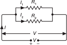
Fig. 1.17 Division of current in two resistors connected in parallel
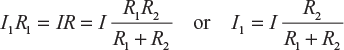
According to Ohm’s law, I1R1 = I2R2 = V or 
Hence, the current in each branch of a parallel circuit is inversely proportional to its resistance. The value of branch current can also be expressed in terms of total circuit current, that is,
I1R1 = I2R2 = IR = V
where R is total or effective resistance of the circuit and I is the total current.
Now,
Similarly,
1.34.2 When Three Resistors are Connected in Parallel
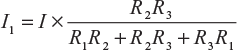
Figure 1.18 shows three resistors having resistance R1, R2, and R3 connected in parallel across a supply voltage of V volt. Let the current in each branch be I1, I2, and I3, respectively.
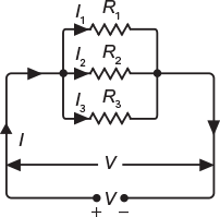
Fig. 1.18 Division of current in three resistors connected in parallel
According to Ohm’s law,
I1R1 = I2R2 = I3R3 = IR = V
Where R is the total or effective resistance of the circuit and I is the total current.
Now,
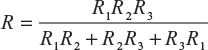
∴
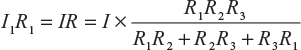
or
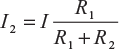
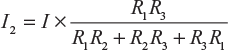
Similarly,
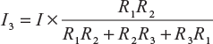
and
A resistor R is connected in series with a parallel circuit comprising of two resistors having resistance of 12 and 8 ohm, respectively. The total power dissipated in the circuit is 96 W applied voltage is 24 V. Calculate the value of R.
Solution:
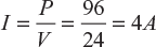
Total power dissipated P = 96 W; applied voltage, V = 24 V
The circuit diagram is shown in Figure 1.19. Equivalent resistance of the two resistances connected in parallel is say RP.
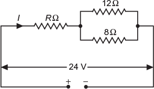
Fig. 1.19 Circuit diagram as per data
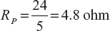
∴
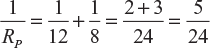
or
Current supplied to the circuit,
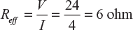
Effective resistance of the circuit,
Now,
REFF = R + RP
∴
R = REFF − RP = 6 – 4.8 = 1.2 ohm (Ans.)
Example 1.14
A circuit consists of three resistances of 12 ohm, 18 ohm, and 3 ohm, respectively, joined in parallel is connected in series with a fourth resistance. The whole circuit is supplied at 60 V and it is found that power dissipated in 12 ohm resistance is 36 W. Determine the value of fourth resistance and the total power dissipated in the group.
Solution:
The circuit diagram is shown in Figure 1.20.
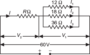
Fig. 1.20 Circuit diagram as per data
Leave a Reply