A simple electric network is shown in Figure 2.1. It contains two voltage sources E1 and E2 and three resistors R1, R2, and R3. In fact, the interconnection of either passive elements or the interconnection of active and passive elements constitute an electric network.
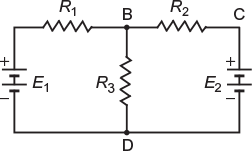
Fig. 2.1 An electric network
2.2.1 Active elements
The elements that supply energy in an electric network are called active elements. In the circuit shown in Figure 2.1, E1 and E2 are the active elements.
Note: When a battery is delivering current from its positive terminal, it is under discharging condition. However, if it is receiving current at its positive terminal, then it is under charging condition. In both the cases, it will be considered as an active element.
2.2.2 Passive Elements
The elements that receive electrical energy and dispose the same in their own way of disposal are called passive elements. In the circuit shown in Figure 2.1, R1, R2, and R3 are the passive elements. The other passive elements that are not used in this circuit are inductors and capacitors.
2.2.3 Network Terminology
Network theorems are applied to analyse the electrical network. While discussing these theorems, we come across the following terms:
- Electric network: A combination of various electric elements connected in any manner is called an electric network.
- Electric circuit: An electric circuit is a closed conducting path through which an electric current either flows or is intended to flow.
- Parameters: The various elements of an electric circuit are called its parameters such as resistors, inductors, and capacitors.
- Linear circuit: An electric circuit that contains parameters of constant value, that is, their value do not change with voltage or current is called linear circuit.
- Non-linear circuit: An electric circuit that contains parameters whose value changes with voltage or current is called non-linear circuit.
- Bilateral circuit: An electric circuit that possesses the same properties or characteristics in either direction is called bilateral circuit. A transmission line is bilateral because it can be made to perform its function equally well in either direction.
- Unilateral circuit: An electric circuit whose properties or characteristics change with the direction of its operation is called unilateral circuit. A diode rectifier circuit is a unilateral circuit because it cannot perform similarly in both the directions.
- Unilateral elements: The elements that conduct only in one direction, such as semi- conductor diode, are called unidirectional elements.
- Bilateral elements: The elements that conduct in both the directions similarly, such as a simple piece of wire (resistor), diac, and triac, are called bilateral elements.
- Active network: An electric network that contains one or more sources of emf is called active network.
- Passive network: An electric network that does not contain any source of emf is called passive network.
- Node: A node is a point in the network where two or more circuit elements are joined. In Figure 2.1, A, B, C, and D are the nodes.
- Junction: A junction is a point in the network where three or more circuit elements are joined. In fact, it is a point where current is divided. In Figure 2.1, B and D are junctions.
- Branch: The part of a network that lies between two junction points is called branch. In Figure 2.1, DAB, BCD, and BD are the three branches.
- Loop: The closed path of a network is called a loop. In Figure 2.1, ABDA, BCDB, and ABCDA are the three loops.
- Mesh: The most elementary form of a loop that cannot be further divided is called a mesh. In Figure 2.1, ABDA and BCDB are the two meshes, but ABCDA is the loop.
Leave a Reply