In fact, a voltage source can be converted into current source and vice versa. Consider a DC source connected to a load resistance RL, as shown in Figure 2.13(a). The source can be treated as a voltage source, as shown in Figure 2.13(b), or as a current source as shown in Figure 2.13(c). Both types of representations appear the same to the externally connected load resistance RL. They must give the same results.
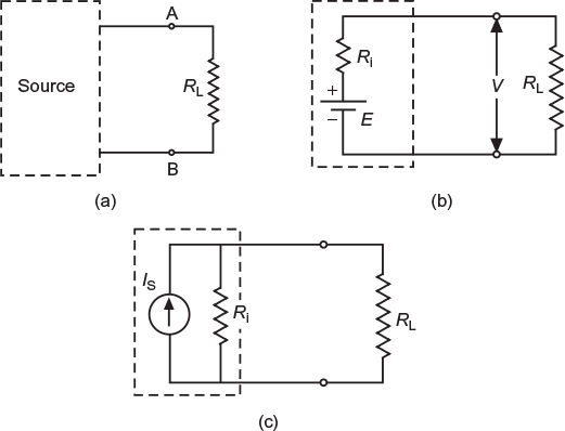
Fig. 2.13 (a) Load connected to source (b) Voltage source and (c) Current source
The source is treated as voltage source as shown in Figure 2.13(b). If the load resistance RL is reduced to zero as shown in Figure 2.14(a), (i.e., the terminal A and B are short circuited), the current supplied by the source is
IL (short circuit) = ![]()
The source is treated as a current source, as shown in Figure 2.13(c). If the load resistance RL is reduced to zero (the same resistance Ri2 connected in parallel with the short circuit is as good as not being present), as shown in Figure 2.14(b). However, the current obtained by shorting the terminals A and B simply source current IS. This current must be the same as supplied by the source when it is treated as voltage source.
IS = IL(short circuit) = ![]()
E = ISRi1 (2.1)
Again, the two representations of the source must give same terminal voltage when the load resistance RL is disconnected from the source (i.e., when the terminals A and B are open circuited).
When the source is treated as voltage source (as shown in Fig. 2.14(c)), the terminal voltage,
V = E
When the source is treated as a current source (as shown in Fig. 2.14(d)), the terminal voltage,
V = ISRi2 = E (2.2)
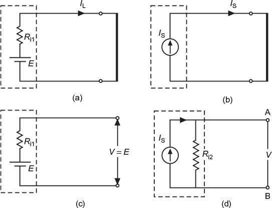
Fig. 2.14 (a) Voltage source on short-circuit (b) Current source on short-circuit (c) Voltage source on open-circuit and (d) Current source on open-circuit
From Equation (2.1) and (2.2), we get
ISRi1 = ISRi2
Ri1 = Ri2 = Ri (say)
Both Equation (2.1) and (2.2) reduce to
E = ISRi (2.3)
Hence, it is seen that in both the representations of the source, the source impedance as faced by the load resistance at the terminal AB is the same (i.e., Ri). Thus, it establishes the equivalence between the voltage source representation and the current source representation under short circuit and open circuit conditions.
We can also test the equivalence at a given load resistance RL. In the case of voltage source representation, as shown in Figure 2.14(b), the current through the load resistance
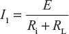
In the case of current source representation, as shown in Figure 2.14(c), the current IS is divided into two branches. Current through the load resistance,

The two currents I1 and I2 are exactly the same. Thus, we conclude that a given voltage source can be converted into its equivalent current source and vice versa by using Equation (2.3).
Example 2.1
Figure 2.15 shows a DC voltage source having an open-circuit voltage of 6 V and an internal resistance of 1Ω. Obtain its equivalent current source representation.
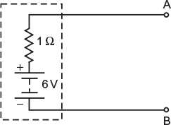
Fig. 2.15 Voltage source
Solution:
If the terminals A and B of voltage source are short circuited, the current supplied by the source,
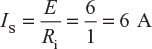
In the equivalent current source representation, the current source is of 6 A. The internal resistance of the source is represented in parallel with the current source as shown in Figure 2.16.
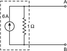
Fig. 2.16 Equivalent current source
Example 2.2
Figure 2.17 shows a DC current source. Obtain its equivalent voltage source representation.
Fig. 2.17 Current source
Solution:
The open-circuit voltage of the current source across the terminals A and B.
E = ISRi = 2 × 100 = 200 V
This will be the generated emf or ideal voltage of the equivalent voltage source representation. The internal impedance (Ri = 100 Ω) is connected in series with the ideal voltage source, as shown in Figure 2.18.
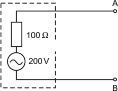
Fig. 2.18 Equivant voltage source
This gives the equivalent voltage source representation of the given current source.
Leave a Reply