Gustav Kirchhoff, a German scientist, summed up his findings in a set of two laws known as Kirchhoff’s laws.
2.5.1 Kirchhoff’s First Law
Since this law relates the currents following through the circuit, it is also known as Kirchhoff’s Current Law (KCL). This law states that the algebraic sum of all the currents meeting at a point or junction is zero.
Mathematically,
ΣI = 0
To determine algebraic sum in Figure 2.19, let us consider the incoming currents as positive and outgoing currents as negative. By applying KCL to junction O in Figure 2.19, we get
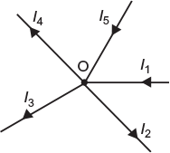
Fig. 2.19 Current of various branches meeting at a junction
I1 − I2 − I3 − I4 + I5 = 0
or
I1 + I5 = I2 + I3 + I4
that is, sum of incoming currents = sum of outgoing currents.
Hence, KCL can also be stated as the sum of incoming currents are equal to the sum of outgoing currents at a point or junction in an electrical network.
2.5.2 Kirchhoff’s Second Law
Since this law relates the voltages in a closed circuit of an electrical network, it is also known as Kirchhoff’s voltage law (KVL) or Kirchhoff’s mesh law. This law states that in a closed circuit or mesh, the algebraic sum of all the emfs and the algebraic sum of all the voltage drops (i.e., product of current and resistances) is zero.
Therefore,
algebraic sum of all the emfs + algebraic sum of all the voltage drops = 0
Mathematically,
ΣE + ΣV = 0 (algebraic values)
As algebraic sum of emf and voltage drops to be taken, we have to determine their signs while tracing a circuit. For this, we always consider a rise in potential as positive and a fall in potential as negative.
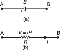
Fig. 2.20 (a) emf of a cell (b) Voltage drop in a resistor
Consider a branch AB containing only one source of emf (E), as shown in Figure 2.20(a). While tracing this branch from A to B, there is fall in potential, and therefore, E is negative. However, if we trace it from B to A, there is rise in potential and E will be positive. In short,
If tracing branch A to B, then E is negative (i.e., −E).
If tracing branch B to A, then E is positive (i.e., +E).
Note: The direction of flow of current is not considered since it has no effect.
To determine the sign for the voltage drop V (= IR), consider a branch containing resistor of resistance R in which current I flows from A to B, as shown in Figure 2.20(b). Therefore, A is at high potential w.r.t. terminal B.
Thus, while tracing branch from A to B, V is negative (i.e., −V) as there is a fall in potential and we are moving in the direction of flow of current. However, while the tracing branch is from B to A, V is positive (i.e., +V) as there is rise in potential and we are moving opposite to the direction of flow of current.
Note: Only the direction of flow of current determines the sign of V.
Illustration: Consider a network shown in Figure 2.21. In this circuit, we can apply KVL for the closed circuit BCDA and form an equation as
−I1 R1 − E2 +I2 R3 = 0
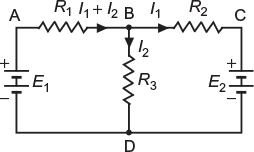
Fig. 2.21 Electric network
where I1R1 (voltage drop) is considered as negative, since we are tracing the circuit along the direction of flow of current. E2 (emf of battery) is taken as negative as we move from positive to negative terminal at the battery and there is fall in potential.
I2R3(voltage drop) in taken as positive as we move opposite to the flow of current.
Similarly, applying KVL to the closed circuit ABDA, we get –(I1 + I2) R1 – I2R3 + E1 = 0
2.5.3 Solution of Network by Kirchhoff’s Laws
When a network is to be solved by applying Kirchhoff’s laws, the following steps are taken:
- Mark the assumed direction of flow of current in various branches of the network according to KCL.
- Choose as many number of closed circuits as the number of unknown quantities.
- Apply KVL to the chosen closed circuits and prepare the equations.
- After solving the equations, determine the unknown values.
Note: If the determined current carries the negative, sign, it shows that the actual direction of flow of current is opposite to that of the assumed direction of flow of current in the given branch.
Leave a Reply