For the first time, Wheatstone (an English telegraph engineer) proposed this bridge for measuring the value of an unknown resistance. This bridge consists of four arms AB, BC, AD, and DC having resistances P, Q, X, and R, respectively (see Fig. 2.22). Resistance P and Q are the known (fixed value) resistances and are called ratio arms. While resistance R is a variable resistance of known value and X is an unknown resistance whose value is to be determined.
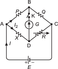
Fig. 2.22 Wheatstone Bridge
To determine the value of X, connect a battery E across A and C and a galvanometer G across B and D through key K. The bridge is said to be balanced, when galvanometer G gives zero defection on closing key K. The balance is obtained by selecting the values of resistors P and Q suitably, and finally, adjusting the value of R.
At balance,
Current flowing through galvanometer = 0
Current flowing through resistor P and Q = I1
Current flowing through resistor X and R = I2
Voltage drop across AB = Voltage drop across AD
I1P = I2 X (2.5)
Voltage drop across BC = Voltage drop across DC
I1Q = I2R (2.6)
Dividing Equation (2.5) by (2.6), we get
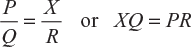
Product of opposite arms = Product of other opposite arms
or

Figure 2.23 shows two batteries connected in parallel, each represented by an emf along with its internal resistance. A load resistance of 6 Ω is connected across the ends of the batteries.
Calculate the current through each battery and the load.
(U.P.T.U. July 2002)
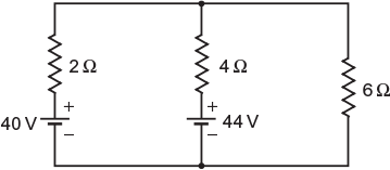
Fig. 2.23 Given network
Solution:
Let the current flowing through various branches be as marked in Figure 2.24.
By applying KVL to mesh ABEFA, we get
−2I1 + 4I2 − 44 + 40 = 0
or
2I1 − 4I2 = 40 − 44 or 2I2 − I1 = 2 (2.7)
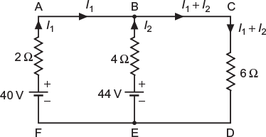
Fig. 2.24 Assumed direction of flow of current in various branches
By applying KVL to the mesh BCDEB, we get
−4I2 − 6 (I1 + I2) + 44 = 0
or
4I2 + 6 (I1 + I2) = 44 or 5I2 + 3I1 = 22 (2.8)
Multiplying Equation (2.7) by 3 and adding with Equation (2.8), we get

Substituting the value of I2 in Equation (2.7), we obtain

Current through load,
Example 2.4
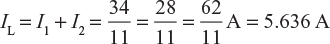
Two batteries A and B are connected in parallel and a load of 10 Ω is connected across their terminals. A has an emf of 12 V and an internal resistance of 2 Ω and B has an emf of 8 V and an internal resistance of 1 Ω. Use Kirchhoff’s laws to determine the magnitude of currents and also the directions in each of the batteries. Further, determine the potential difference across external resistance.
(U.P.T.U. Tut.)
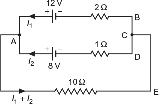
Fig. 2.25 Circuit as per given data
Let the current flowing through various branches be as marked in Figure 2.25.
By applying KVL to mesh ABCDA, we get
2I1 − I2 + 8 − 12 = 0
or
2I1 − I2 = 12 − 8
or
2I1 − I2 = 4 (2.9)
By applying KVL to mesh ADCEA, we get
I2 + 10 (I1 + I2) − 8 = 0
or
10I1 + 11I2 = 8 (2.10)
Solving Equations (2.9) and (2.10), we get
I1 = 1.625 A
and
I2 = −0.75 A
The negative sign with current I2 shows that current I2 is flowing opposite to the assumed direction.
Current flowing through the load resistance of 10 Ω = I1 + I2 = 1.625 + (−0.75) = 0.875 A
Potential difference across load resistance = (I1 + I2) R = 0.875 × 10 = 8.75 V
Example 2.5
By using Kirchhoff’s laws, find the current in XY in the circuit shown in Figure 2.26.
Fig. 2.26 Given network
Solution:
The assumed direction of flow of current in various sections is marked in Figure 2.27.
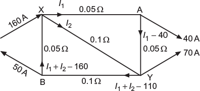
Fig. 2.27 Assumed direction of flow of current in various branches
By applying Kirchhoff’s second law, we get
Circuit XYAX
−0.05I1 −0.05 (I1 − 40) + 0.1I2 = 0
−0.05I1 − 0.05I1 + 2 + 0.1I2 = 0
or
I1 – I2 = 20 (2.11)
−0.1I2 − 0.1 (I1 + I2 − 110) − 0.05 (I1 + I2 − 160) = 0
or
−0.1I2 − 0.1I1 − 0.1I2 + 11− 0.05I1 − 0.05I2 + 8 = 0
or
−0.15I1 − 0.25I2 + 19 = 0
or
3I1 + 5I2 = 380 (2.12)
Multiplying Equation (2.11) by 3 and subtracting from (2.12), we get
8I2 = 320
Current in section XY, ![]()
Example 2.6
In Figure 2.28, the potential of point A is –30 V. Using Kirchhoff’s laws, find (a) value of V and (b) power dissipated by 5 Ω resistance.
(U.P.T.U. Tut.)
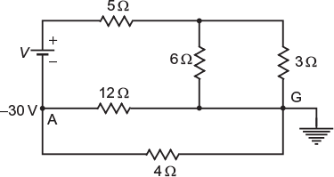
Fig. 2.28 Given network
Solution:
The potential at point A is –30 V and potential at point G is zero, being grounded. Potential difference across 12-Ω resistor = 30 V
Current through 12-Ω resistor ![]()
A simplified circuit of the network and assumed current distributed is shown in Figure 2.29.
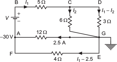
Fig. 2.29 Assumed direction of flow of current in various branches
By applying KVL to mesh CDEC, we get
−3 (I1 − I2) + 6I2 = 0
or
−3I1 + 3I2 + 6I2 = 0 or I1 = 3I2 (2.13)
By applying KVL to mesh AGEFA, we get
12 × 2.5 − 4 (I1 − 2.5) = 0
or
30 − 4I1 + 10 = 0 or I1 = 10 A
From Equation (2.13),
By applying KVL to mesh ABCGA, we get
V – 5I1 – 6I2 – 2.5 × 12 = 0
or
![]() or V = 100 V
or V = 100 V
Power dissipated in 5-Ω resistor = ![]() × 5 = (10)2 × 5 = 500 W
× 5 = (10)2 × 5 = 500 W
Example 2.7
In the circuit shown in Figure 2.30, find the value of IS for I = 0.
(U.P.T.U. Tut.)
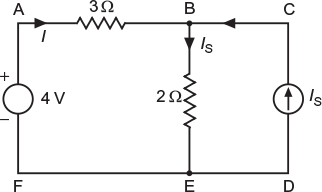
Fig. 2.30 Given network
Solution:
By applying KCL at junction B, we get
Current through branch BE (i.e., 2-Ω resistor)
= I + IS = 0 + IS = IS (I = 0)
By applying KVL to mesh ABEFA, we get
–3I1 – 2IS + 4 = 0
or
3I + 2IS = 4
or
Example 2.8
Find the value of R and the current through it in the circuit shown in Figure 2.31, when the current is zero in branch OA.
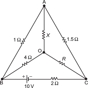
Fig. 2.31 Given network
Solution:
Since current flowing through branch OA is zero, the same current I1 flows through branch BA and AC. The assumed direction of flow of current in other branches is also marked in Figure 2.32, according to Kirchhoff’s first law.
Fig. 2.32 Assumed direction of flow of current in various branches
By applying Kirchhoff’s second law to the following meshes, we get
Mesh BAOB
–I1 ± 0 + 4I2 = 0
I1 = 4I2 (2.14)
Mesh BACB
–I1 – 1.511 – 2 (I1 + I2) + 10 = 0
4.5I1 + 2I2 = 10
Substituting the value of I1 from Equation (2.14), we get
4.5 (4I2) + 2I2 = 10
or
I2 = 0.5 A
and
I1 = 4 × 0.5 = 2 A
Mesh BOCB
–4I2 – RI2 – 2 (I1 + I2) + 10 = 0
or
–4 × 0.5 – R × 0.5 – 2 (2 + 0.5) + 10 = 0
or
R = 6 Ω
Example 2.9
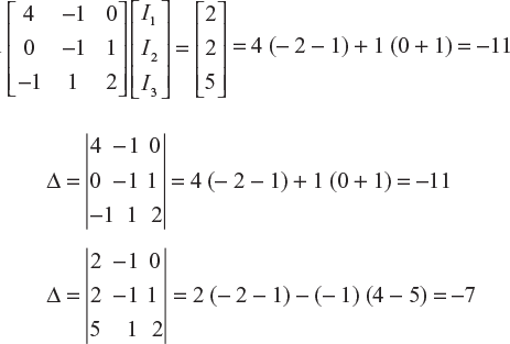
Determine the current in the 4-Ω resistance of circuit shown in Figure 2.33.
(U.P.T.U. Tut.)
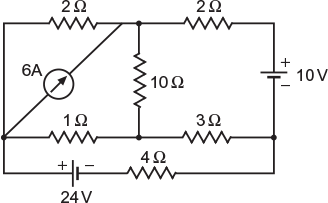
Fig. 2.33 Given network
Solution:
A simplified circuit is redrawn as shown in Figure 2.34. Let the current flowing through various branches be as marked in Figure 2.34.
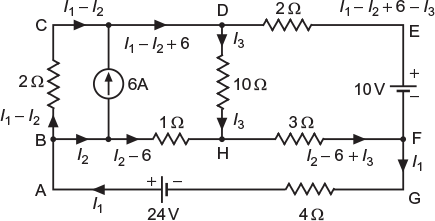
Fig. 2.34 Assumed direction of flow of current in various branches
By applying KVL to various meshes, that is, BCDHB, DEFHD, and BHFGAB, we get
–2 (I1 – I2) – 10I3 + 1 × (I2 – 6) = 0; (2.15)
–2 (I1 – I2 + 6 – I3) + 3 (I2 – 6 + I3) + 10I3 = +10 (2.16)
and −1 × (I2 − 6) − 3 (I2 − 6 + I3) − 4I1 = −24 (2.17)
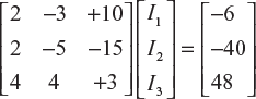
From Equation (2.15), 2I1 − 3I2 + 10I3 = −6 (2.18)
From Equation (2.16), 2I1 − 5I2 − 15I3 = −40 (2.19)
From Equation (2.17), 4I1 + 4I2 + 3I3 = 48 (2.20)
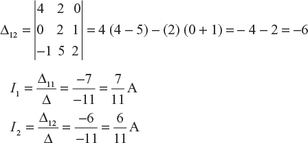
Solving equations by matrices:
The abovementioned equations can be given in the matrix form as
The common determinant is given as
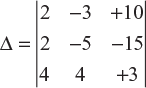
= 2 [(−5) × 3 − 4 × (−15)] − 2 [(−3) × 3 − 4 × 10] + 4 [(−3) × (−15) − (−5) × 10]
= 2 [−15 + 60] − 2 [−9 − 40] + [45 + 50]
= 90 + 98 + 380 = 568
The determinant for I1 is given as
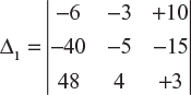
= − 6 [(−5) × 3 − 4 × (−15)] + 40 [(−3) × 3 − 4 × 10] + 48 [(−3) × (−15) − (−5) × 10]
= − 6 [−15 + 60] + 40 [−9 − 40] + 48 [45 + 50]
= − 270 − 1,960 + 4,560 = 2,330
As per Cramer’s rule, ![]()
Example 2.10
What is the difference of potential between X and Y in the network shown in Figure 2.35.
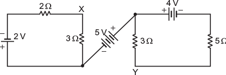
Fig. 2.35 Given network
Refer to Figure 2.36. Let the current in branch AX be I1 and in branch BY be I2.
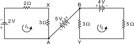
Fig. 2.36 Current in different loops
Current, ![]()
Current, ![]()
Rise in potential from X to Y is given as
VXY = 3 × 0.4 + 5 − 3 × 0.5 = 4.7 V
Example 2.11
Find the total power delivered to the circuit by two sources in Figure 2.37.
(U.P.T.U. Tut.)
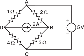
Fig. 2.37 Given network
Solution:
Let the current flowing through different branches be as marked in Figure 2.38.
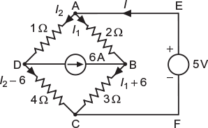
Fig. 2.38 Assumed direction of flow of current in various branches
By applying KVL to mesh ABCFEA, we get
− 2I1 − (I1 + 6) × 3 − 5 = 0 or ![]()
By applying KVL to mesh ADCFEA, we get
−I2 − 4 (I2 − 6) − 5 = 0 or ![]()
Total power delivered by the two sources
= Total power absorbed by various resistors
= I12 × 2 + (I1 + 6)2 × 3 + (I2 − 6)2 × 4 + I22 × 1
= (−2.6)2 × 2 + (−2.6 + 6)2 × 3 + (5.8 − 6)2 × 4 + (5.8)2 × 1
= 82 W
Example 2.12
In the circuit shown in Figure 2.39, determine the value of E2 that will reduce the galvanometer current to zero. The galvanometer resistance is 10 Ω.
Fig. 2.39 Given network
Solution:
By applying KCL, the direction of flow of current in various branches is marked in Figure 2.40. Since galvanometer does not carry any current, the current in branch BC is the same as that in branch AB, that is, I1. Similarly, current flowing through branch DC is the same as that in branch AD, that is, I2.
Fig. 2.40 Assumed direction of flow of current in various branches
By applying KVL to various meshes, we get:
Mesh ABCDA
−11I1 + 9I2+E2 = 0
or
11I1 − 9I2 = E2 (2.21)
Mesh ABCE1A
−11I1 − 2 (I1+I2) + 2 = 0
or
13I1 + 2I2 = 2 (2.22)
Mesh BCDB
−5I1 + 4I2 = 0
or
I1 = 0.8I2 (2.23)
Substituting the value of I1 in Equation (2.23), we get
13 (0.8I2) + 2I2 = 2
or
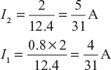
Substituting the value of I1 and I2 in Equation (2.21), we get
11 × (4/31) − 9 (5/31) = E2
or
Note: The negative sign shows that the cell E2 should be connected in reverse direction.
Example 2.13
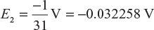
Determine the current I in 4-Ω resistance in the circuit shown in Figure 2.41.
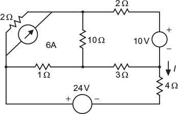
Fig. 2.41 Given network
Solution:
A simplified circuit is shown in Figure 2.42. By applying KCL, different currents are marked in various sections.
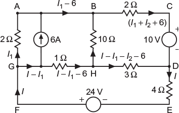
Fig. 2.42 Assumed direction of flow of current in various branches
By applying KVL to various loops, we get
Loop ABHGA:
10I2 + (I − I1 − 6) − 2I1 = 0 or I − 3I1 + 10I2 = 6 (2.24)
Loop BCDHB:
−2 (I1+ I2 + 6) − 10 + 3 (I − I1− I2 − 6) − 10I2 = 0
3I − 5I1 − 15I2 = 40 (2.25)
Loop GHDEFG:
−(I − I1 − 6) − 3 (I − I1− I2 − 6) − 4I + 24 = 0
or
8I − 4I1 − 3I2 = 48 (2.26)
Eliminating I1 from Equations (2.24) and (2.25), we get
4I − 95I2 = 90 (2.27)
Eliminating I1 from Equations (2.25) and (2.26), we get
28I + 45I2 = 80 (2.28)
Eliminating I2 from Equations (2.27) and (2.28), we get
568I = 2330
Therefore, current in 4-Ω resistor, I = 4.102 A
Alternatively, the three equation are as follows:
I − 3I1 + 10I2 = 6
3I − 5I1 − 15I2 = 40
8I − 4I1 − 3I2 = 48
The three equations can be solved by the method of determinants, that is, by applying Cramer’s rule. The matrix from of the abovementioned equation is
2.7 MAXWELL’S MESH CURRENT METHOD (LOOP ANALYSIS)
In this method, mesh or loop currents are taken instead of branch currents (as in Kirchhoff’s laws). The following steps are taken while solving a network by this method:
- The whole network is divided into number of meshes. Each mesh is assigned a current having continuous path (current is not split at a junction). These mesh currents are preferably drawn in clockwise direction. The common branch carries the algebraic sum of the mesh currents flowing through it.
- Write KVL equation for each mesh using the same signs as applied to Kirchhoff’s laws.
- Number of equations must be equal to the number of unknown quantities. Solve the equations and determine the mesh currents.
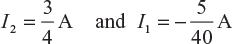
Example 2.14
Using loop current method, find the current I1 and I2 as shown in Figure 2.43.
(U.P.T.U. 2005–06)
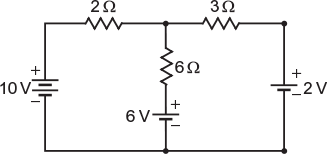
Fig. 2.43 Given network
Solution:
Let the current flowing through the two loops be I1 and I2, as shown in Figure 2.44.
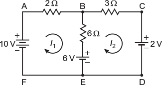
Fig. 2.44 Loop currents in various sections
By applying KVL to different loops, we get
Loop ABEFA
−2I1 − 6 (I1− I2) − 6 + 10 = 0
8I1 − 6I2 = 4
4I1 − 3I2 = 2 (2.29)
Loop BCDEB
−3I2 − 2 + 6 − 6 (I2− I1) = 0
−6I1 + 9I2 = 4 (2.30)
Multiplying Equation (2.29) by 3 and Equation (2.30) by 2, we get
12I1 − 9I2 = 6 (2.31)
−12I1 + 18I2 = 8 (2.32)
Adding Equations (2.31) and (2.32), we get
Example 2.15
Using mesh equation method, find current in the resistance R1 of the network shown in Figure 2.45.
(U.P.T.U. 2004–05)
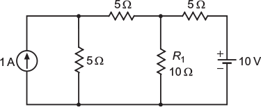
Fig.2.45 Given network
Solution:
Converting current source of 1 A and internal resistance 5 Ω into voltage source,
emf of voltage source, V = I × R = 1 × 5 = 5 V
Internal resistance of voltage source, R = R = 5 Ω
The circuit is shown in Figure 2.46.
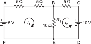
Fig. 2.46 Loop currents in various sections
In mesh ABEFA, I1 (5 + 5) + 10 (I1+ I2) = 5 or 20I1 + 10I2 = 5
4I1 + 2I2 = 1 (2.33)
In mesh BCDEB, 5I2 + 10 (I1+ I2) = 10 or 10I1 + 15I2 = 10
2I1 + 3I2 = 2 (2.34)
Solving Equations (2.33) and (2.34), we get
Current through ![]()
= 0.625 A (from B to E)
Using mesh current method, determine current Ix in the circuit shown in Figure 2.47.
(U.P.T.U. 2005–06)

Fig. 2.47 Given network
Solution:
Let the circuit be as shown in Figure 2.48. Suppose voltage across 2 A current source is Vx,
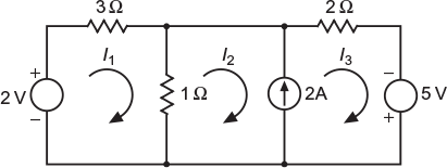
Fig. 2.48 Loop currents in various sections
By applying KVL in mesh 1; 3I1 + (I1− I2) = 2
4I1− I2 = 2 (2.35)
By applying KVL in mesh 2; (I2− I1) + Vx = 0
I1 − I2 = Vx (2.36)
By applying KVL in mesh 3; 2I3 = 5 + Vx (2.37)
Further,
I3− I2 = 2 (2.38)
From Equations (2.36) and (2.37) 2I3 = 5 + (I1− I2)
or
− I1+ I2 + 2I3 = 5 (2.39)
From Equations (2.35), (2.38), and (2.39),
In matrix form
Current, ![]()
Leave a Reply