
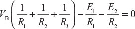
In this method, one of the nodes is taken as the reference node and the other as independent nodes. The voltages at the different independent nodes are assumed and the equations are written for each node as per KCL. After solving these equations, the node voltages are determined. Then, the branch currents are determined.
Consider a circuit shown in Figure 2.49, where D and B are the two independents nodes. Let D be the reference node and the voltage of node B be VB.
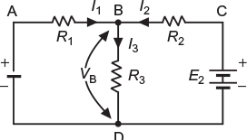
Fig. 2.49 Network with Node B and D
According to KCL,
I1+ I2 = I3 (2.40)
In mesh ABDA, the potential difference across R1 is E1− VB
In mesh BCDB, the potential difference across R2 is E2− VB
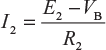
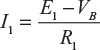
Further, current, 
Substituting these values in Equation (2.40), we get
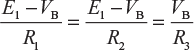
Rearranging the terms,
Since all other value are known, except VB, calculate the value of VB. Then, determine the value of I1, I2, and I3. This method is faster as the result are obtained by solving lesser number of equations.
Example 2.17
Find the current I1 and I2 in the passive elements of the network shown in Figure 2.50.
(U.P.T.U. Tut.)
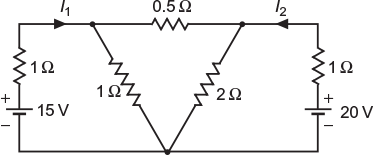
Fig. 2.50 Given network
Solution:
The independent nodes are A, B, and C. Let C be the reference node and VA and VB be the voltages at node A and B, respectively. Let us assume the direction of flow of current as in Figure 2.51.
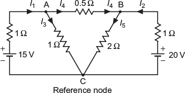
Fig. 2.51 Assumed direction of flow of current in various branches
For node A, ![]() and
and ![]() , assuming VA > VB
, assuming VA > VB
Similarly for node B, ![]() and
and ![]()
Now, by applying KCL to node A, we get
I1 = I4+ I3
or

By applying KCL at node B, we get
I2 + I4 = I5
or

Solving Equations (2.41) and (2.42), we get
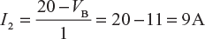
VA = 9.25 V and VB = 11 V
Current ![]()
Two batteries A and B are connected in parallel to a load of 10 Ω. Battery A has an emf of 12 V and an internal resistance of 2 Ω and battery B has an emf of 10 V and internal resistance of 1 Ω. Using nodal analysis, determine the currents supplied by each battery and load current.
(U.P.T.U. Dec. 2003)
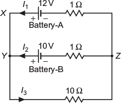
Fig. 2.52 Given network
Solution:
Considering node Z as reference node and the potentials of nodes X and Y be VX and VY, respectively. The assumed current distribution is shown in Figure 2.52.
For node X,
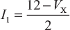
For node Y,
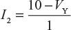
and

By applying KCL to node B, we get
I1+ I2 = I3 or ![]() (2.43)
(2.43)
Moreover,
VX = VY (2.44)
Solving Equations (2.43) and (2.44), we get
VX = VY = 10 V
Thus, current supplied by battery ![]()
Current supplied by battery ![]()
Load current, ![]()
Example 2.19
Using nodal analysis, find current I through 10-Ω resistor in Figure 2.53.
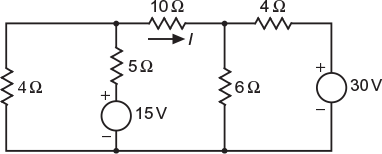
Fig. 2.53 Given network
Solution:
The independent nodes are A, B, and C. Let C be the reference node and VA and VB be the voltages at node A and B, respectively. Let us assume the direction of flow of current is as marked in Figure 2.54. By applying KCL at node A, we get
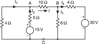
Fig.2.54 Assumed direction of flow of current in various branches
I1+ I2 = I
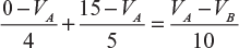
or
−5VA + 60 − 4VA = 2VA − 2VB or 11VA −2VB = 60 (2.45)
By applying KCL at node B, we get
I = I4+ I3
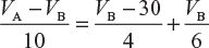
or
12VA − 12VB = 30VB − 900 + 20VB
or
12VA − 62VB = −900 (2.46)
Solving Equation (2.45) and (2.46), we get
VA = 8.39 V and VB = 16.14 V
Current,
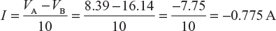
I = 0.775 A (from B to A)
Example 2.20
Calculate currents in all the resistors of the circuit shown in Figure 2.55 using node analysis method.
(U.P.T.U. 2006–07)
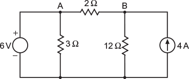
Fig. 2.55 Given network
Solution:
The independent nodes are A, B, and C. Let C be the reference node and VA and VB be the voltages at node A and B, respectively. Let us assume the direction of flow of current is marked as in Figure 2.56.
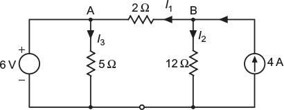
Fig. 2.56 Assumed direction of flow of current in various branches
Here,
VA = 6 V
By applying KCL at node B, we get
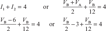
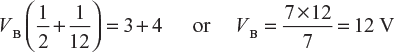
Current in 12-Ω resistor,
Current in 2-Ω resistor,
Current in 3-Ω resistor,
Example 2.21
Use nodal analysis to find the current in various resistors of the circuit shown in Figure 2.57.
(U.P.T.U. 2005–06)
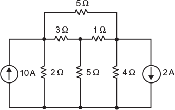
Fig. 2.57 Given network
Solution:
The independent nodes are A, B, C, and D. Let D be the reference node and VA, VB, and VC be the voltages at nodes A, B, and C, respectively, The current flowing through various branches are marked in Figure 2.58.
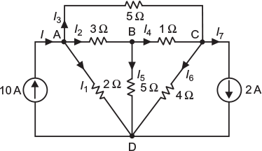
Fig. 2.58 Assumed direction of flow of current in various branches
By applying KCL at different nodes, different node voltage equations are obtained as follows:
Node A
I1 + I2 + I3 = I
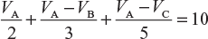
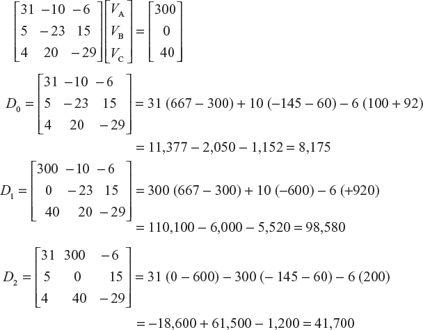
15VA+ 10(VA−VB) + 6(VA−VC) = 300 or 31VA − 10VB − 6VC = 300 (2.47)
Node B
I2 − I4 − I5 = 0
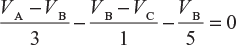
5(VA − VB) − 15(VB − VC) − 3VB= 0 or 5VA − 23VB + 15VC = 0 (2.48)
Node C
I3 + I4 − I6− I7 = 0
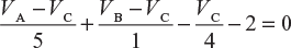
4(VA − Vc) + 20(VB − VC) − 5Vc − 40 = 0 or 4VA + 20VB − 29Vc = 40 (2.49)
The three equations in matrices form are:
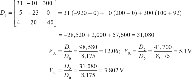
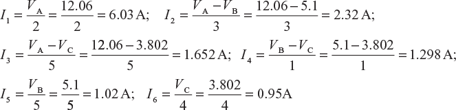
Current in various resistors:
Example 2.22
Using nodal analysis, determine current in each branch of the network as shown in Figure 2.59. Further, find total power loss in the network.
(U.P.T.U. Feb. 2002)
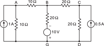
Fig. 2.59 Given network
Solution:
Redraw the circuit and mark the arbitrary assumed values of currents in various branches as shown in Figure 2.60. Let G (or D) be the reference node.
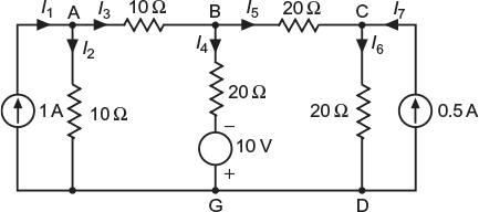
Fig. 2.60 Assumed direction of flow of current in various branches
By applying KCL at different nodes, we get
At node A
I1 = I2 + I3
or

At node B
I3 = I4+ I5 or ![]()
or
2VA − 4VB + VC = 10 (2.51)
At node C
I5 + I7 = IC
or

Solving Equations (2.50), (2.51), and (2.52), we get
VA = 6 V, VB = 2 V, and VC = 6 V
Current through different branches:
Current through current source, I1 = 1 A
Current through branch AG (10-Ω resistor), ![]()
Current through branch AB (10-Ω resistor), ![]()
Current through branch BG (20-Ω resistor), ![]()
Current through branch BC (20-Ω resistor), ![]()
Current through branch CG (20-Ω resistor), ![]()
Current through current source, I7 = 0.5 A
Total power loss = (0.6)2 × 10 + (0.4)2 × 10 + (0.6)2 × 20 + (0.2)2 × 20 + (0.3)2 × 20
= 3.6 + 1.6 + 7.2 + 0.8 + 1.8 = 15 W
Example 2.23
Use the node voltage method to solve the mesh currents in the network shown in Figure 2.61.
(U.P.T.U. June 2001)
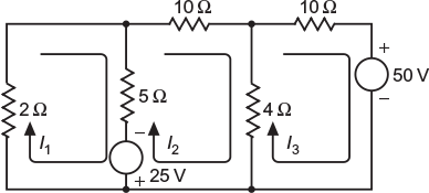
Fig. 2.61 Given network
Solution:
Redraw the circuit and mark the arbitrary assumed values of currents in various branches, as shown in Figure 2.62. Let C be the reference node.
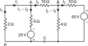
Fig. 2.62 Assumed direction of flow of current in various branches
By applying KCL at different nodes, we get
At node A: ![]() considering VA > VB
considering VA > VB
or
8VA − VB = 50 (2.53)
At node B: ![]()
or
2VA − 17 VB = −500 (2.54)
Multiplying Equation (2.54) by 4 and subtracting it from Equation (2.53), we get
VA = 10.0746 V
Substituting the value of VA in Equation (2.53), we get
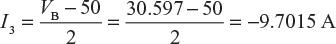
VB = 30.597 V
Various currents of the network
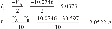
and
Example 2.24
By applying KCL, determine current Is in the electric circuit at Figure 2.63. Take V0 = 16 V
(U.P.T.U. Feb. 2001)
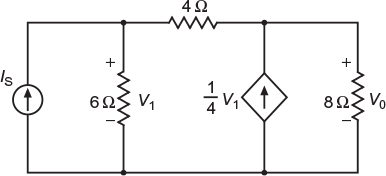
Fig. 2.63 Given network
Solution:
Let the current flowing through the various branches of the circuit be as shown in Figure 2.64.
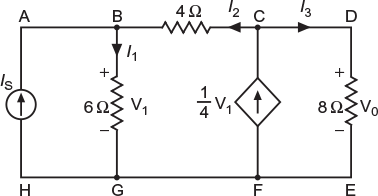
Fig. 2.64 Assumed direction of flow of current in various branches
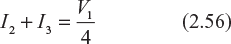
By applying KCL to node B, we get
I2 + IS = I1 (2.55)
By applying KCL to node C, we get
Voltage at node C = V0 = 16 V
4I2 + V1 = 16 (2.57)
In branch BG, ![]() or V1 = 6I1 (2.58)
or V1 = 6I1 (2.58)
In branch DE, ![]()
Substituting the value of I3 and V1 in Equation (2.56), we get

Substituting the value of V1 = 6I1, we get
4I2 + 6I1 = 16 or 3I1 + 2I2 = 8 (2.60)
Solving Equations (2.59) and (2.60), we get
6I1 = 12 or I1 = 2 A and I2 = 1 A
From Equation (2.55), we get IS = I1 – I2 = 2 – 1 = 1 A
whereas V1 = 6I1 = 6 × 2 = 12 V
Leave a Reply