
A single cell can supply a very low current at low voltage. Generally, to operate electrical and electronic circuits, a large current at high voltage is required. Therefore, a number of cells are connected in series, parallel, and series–parallel grouping.
4.5.1 Series Grouping
When a number of cells are connected in such a way that the negative terminal of one is connected to positive terminal of the other and so on, as shown in Figure 4.2, the cells are said to be connected in series grouping.
Where
n = No. of cell connected in series;
E = emf of each cell;
r = Internal resistance of each cell;
R = Load resistance.
Total emf of the grouping = n × E
Total internal resistance of the grouping = n × r
Total resistance of the circuit = R + n × r
Current delivered to the load, ![]()
This grouping is used where higher voltages are required.
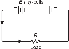
Fig. 4.2 Cells connected in series
4.5.2 Parallel Grouping
When a number of cells are connected in such a way that the positive terminals of all the cells are connected together and negative terminals are connected together separately, as shown in Figure 4.3, the cells are said to be connected in parallel grouping.
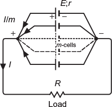
Fig. 4.3 Cells connected in parallel
Where
m = No. of cells connected in parallel;
E = emf of each cell;
r = Internal resistance of each cell;
R = Load resistance.
Total emf of the grouping = E
Total resistance of the grouping = r/m
Total resistance of the circuit = R + (r/m)
Current delivered to the load, ![]()
Current supplied by each cell = I/m
This grouping is used where higher currents are required.
4.5.3 Series–Parallel Grouping
The grouping in which a number of cells are connected in series in one row and a number of such rows are connected in parallel is called a series–parallel grouping of cells.
Figure 4.4 shows a series–parallel grouping of cells.
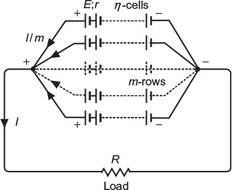
Fig. 4.4 Cells connect in series-parallel
Where,
n = No. of cells connected in series in each row;
E = e.m.f. of each cell;
r = Internal resistance of each cell;
m = No. of rows connected in parallel;
R = Load resistance.
Total emf of each row or grouping = n × E
Total internal resistance of each row = n × r
Total internal resistance of grouping = n × r/m
Total resistance of the circuit = R (n × r/m)
Current delivered to the load, ![]()
Current supplied by each row ![]()
The current supplied by a series–parallel grouping will be maximum when
Load resistance = Internal resistance of the grouping
i.e.,

This grouping used where both higher currents and higher voltages are required.
Example 4.1
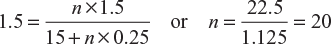
How many cells, each having an emf of 1.5 V and internal resistance of 0.25 Ω would be required (connected in series) to pass a current of 1.5 A through a resistance of 15 Ω.
Solution:
Let n be the number of cells connected in series:
Current delivered to the load, ![]()
Here, E = 1.5 V; R = 15 Ω; r = 0.25 Ω, and I = 1.5 A
∴
Example 4.2
Four dry cells each of which has an emf of 1.5 V and an internal resistance of 0.06 Ω are connected in parallel. Determine current and power dissipated in the external load resistance of 2.985 Ω.
Solution:
In parallel circuit
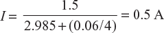
Current delivered to load resistance, ![]()
Here, E = 1.5 V; R = 2.985 Ω; r = 0.06 Ω, and m = 4
Power dissipated in external load resistor
= I2 × R = (0.5)2 × 2.985 = 0.74625 W
Example 4.3
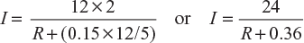
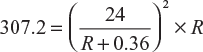
Four batteries are connected in parallel to supply current to a resistive load for heating. Each battery consists of 12 cells connected in series. The emf of each cell is 2 V and internal resistance 0.15 Ω. What should be the resistance of the load so that power consumed in the load is 307.2 W?
Current supplied by series – parallel grouping

Here, n = 12; E = 2 V; m = 5; r = 0.15
Power consumed in the load resistor, P = I2 × R
or R2 + 0.72 R + 0.1296 = 1.875 R or R2 − 1.155 R + 0.1296 = 0
or 
Substituting the value of R in Equation (4.1), we get
I = 17.28 A or 49.39 A
4.6 BATTERY
A series, parallel, or series–parallel grouping of cells is called a battery.
Generally, a cell can deliver a small current at low voltage. For a circuit, if higher voltage is required, a battery containing number of cells connected in series is applied; if higher current is required, a battery containing number of cells connected in parallel is applied; if larger current at higher voltage is required, a battery containing number of cells in series further connected in parallel is applied.
Usually, a number of cells connected in series placed in a single container are called a battery.
4.6.1 Lead–Acid Battery
Figure 4.5(a) shows the cut-away view of 6 V commercial lead–acid battery. The following are the important parts of the battery.
- Container: It is the outer body of the battery. It is made of a hard rubber or plastic material and is sealed at the top to prevent spilling of the electrolyte. A large space is left at the bottom of the container so that the sediments that drop from the plates are collected here and may not short circuit the positive and negative plates.
- Plates: Generally, alloy of lead–antimony sheets covered with lead peroxide and spongy lead forming positive and negative plates, respectively, are used as electrodes. To increase the capacity of the battery, we use a large number of plates in each cell instead of only two plates. The number of positive2 and negative plates (i.e., 11, 13, 15, or 17) of each cell are alternatively placed and sandwiched with an insulator called separator as shown in Figure 4.5(b). One group of positive and negative plates forms a cell which develops an emf of 2.0 V. A separate compartment is provided for each cell in the container of the battery.
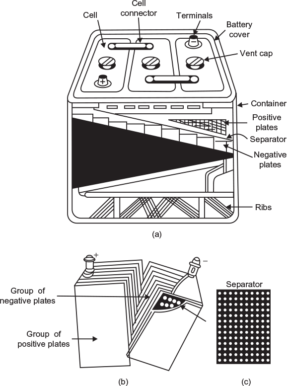 Fig. 4.5 Constructional features of a lead-acid battery (a) Sectional view of a lead-acid battery (b) Battery plates (c) Separator
 - Separator: To reduce the internal resistance of the cell and to save the space, the plates are placed very close to each other. To prevent the plates touching each other if they wrap or buckle, they are separated by a rubber sheet (non-conducting material) having large number of small holes called separator (Fig. 4.5(c)).
- Electrolyte: Dilute sulphuric acid (H2SO4) is used as an electrolyte in lead–acid batteries. Sulphuric acid is added to water in such a proportion that with a fully charged battery, its specific gravity is about 1.28 to 1.29.
- Battery cover: Each cell compartment is covered usually with a moulded hard rubber and the joints between covers and container are sealed with an acid-resistant material. In each cell cover, openings are provided—two for positive and negative terminals, and third for a vent. The whole container is fitted with a leak proof cover.
- Vent caps: The vent cap has a vent hole that allows free exit of the gases formed in the cell during charging. The vent caps can be easily removed to add water. The vent cap is also removed to insert the nozzle of hydrometer for checking the specific gravity of electrolyte used to analyse the battery charge condition.
- Inter-cell connector: The cells, placed in the same container, are connected in series with a lead alloy link called intercell connector.
- Cell terminals: Each cell has two terminals that are generally made of lead as it does not corrode due to the electrolyte. The positive terminal of the battery is marked with a red colour or by a large positive (+ ) sign.
Leave a Reply