The complete assembly of various parts in a scattered form of a DC machine is shown in Figure 11.4. The essential parts of a DC machine are described as follows:
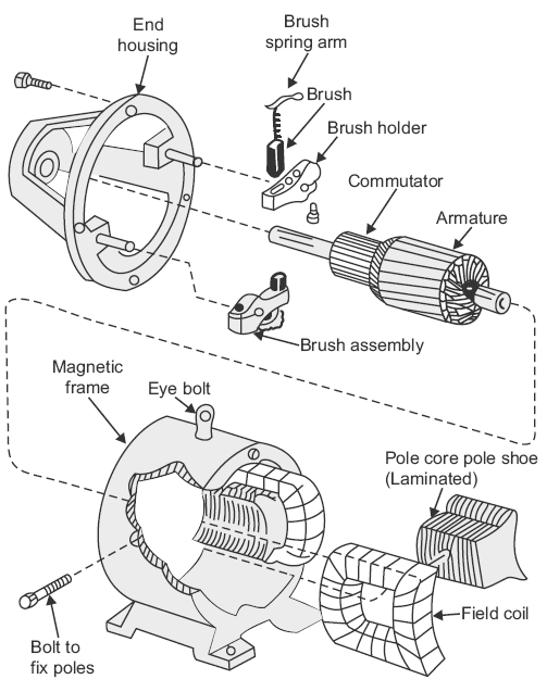
Fig. 11.4 Main parts of DC machine
- Magnetic frame or yoke: The outer cylindrical frame to which main poles and inter-poles are fixed and by means of which the machine is fixed to the foundation is called the yoke. It serves the following two purposes:
- It provides mechanical protection to the inner parts of the machine.
- It provides a low reluctance path for the magnetic flux.
- Pole core and pole shoes: The pole core and pole shoes are fixed to the magnetic frame or yoke by bolts. They serve the following purposes:
- They support the field or exciting coils.They spread out the magnetic flux over the armature periphery more uniformly.Since pole shoes have large X-section, the reluctance of magnetic path is reduced. Usually, the pole core and pole shoes are made of thin cast steel or wrought iron laminations that are riveted together under hydraulic pressure as shown in Figure 11.5.
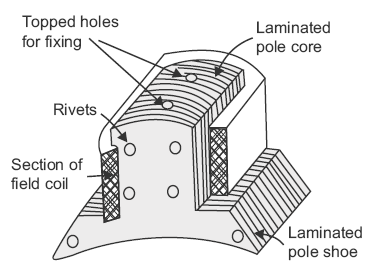 Fig. 11.5 Pole core and pole shoe
 - Field or exciting coils: Enamelled copper wire is used for the construction of field or exciting coils. The coils are wound on the former (see Fig. 11.6) and then placed around the pole core as shown in Figure 11.5. When DC is passed through the field winding, it magnetises the poles that produce the required flux. The field coils of all the poles are connected in series in such a way that when current flows through them, the adjacent poles attain opposite polarity as shown in Figure 11.7.
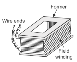 Fig. 11.6 Field winding
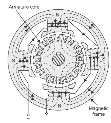 Fig. 11.7 Connections of field winding
 - Armature core: It is cylindrical in shape and keyed to the rotating shaft. At the outer periphery, slots are cut, as shown in Figure 11.8, and they accommodate the armature winding. The armature core shown in Figure 11.8 serves the following purposes:
- It houses the conductors in the slots.It provides an easy path for magnetic flux.
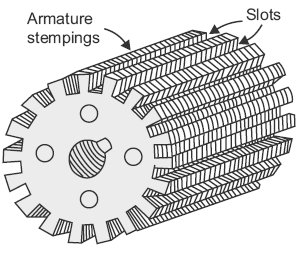 Fig. 11.8 Armature core
 - Armature winding: The insulated conductors housed in the armature slots are suitably connected. This is known as armature winding. The armature winding is the heart of a DC machine. It is a place where conversion of power takes place, that is, in the case of generator, mechanical power is converted into electrical power; while in the case of motor, electrical power is converted into mechanical power. On the basis of connections, there are two types of armature windings, namely lap winding and wave winding.
- Lap winding: In lap winding, the conductors are connected in such a way that the number of parallel paths are equal to the number of poles. Thus, if machine has P poles and Z armature conductors, then there will be P parallel paths and each path will have Z/P conductors in series. In this case, the number of brushes is equal to the number of parallel paths. Out of which, half the brushes are positive and the remaining (half) are negative.
- Wave winding: In wave winding, the conductors are so connected that they are divided into two parallel paths, irrespective of the number of poles of the machine. Thus, if machine has Z armature conductors, there will be only two parallel paths each having Z/2 conductors in series. In this case, the number of brushes is equal to two, that is, number of parallel paths.
- Commutator: It is the most important part of a DC machine and serves the following purposes:
- It connects the rotating armature conductors to the stationary external circuit through brushes.It converts the AC induced in the armature conductors into unidirectional current in the external load circuit during the generator action, whereas it converts the alternating torque into unidirectional (continuous) torque produced in the armature during the motor action.
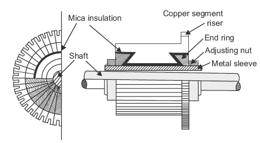 Fig. 11.9 Commutator
 - Brushes: The brushes are pressed upon the commutator and form the connecting link between the armature winding and the external circuit. They are usually made of high grade carbon because carbon is a conducting material, and at the same time, in powdered form, it provides imbricating effect on the commutator surface. The brushes are held in particular position around the commutator by brush holders and rocker.
- Brush rocker: It holds the spindles of the brush holders. It is fitted on to the stationary frame of the machine with nut and bolts. By adjusting its position, the position of the brushes over the commutator can be adjusted to minimise the sparking at the brushes.
- End housings: End housings are attached to the ends of the main frame and support bearings. The front housing supports the bearing and the brush assemblies, whereas the rear housing usually supports the bearing only.
- Bearings: The ball or roller bearings are fitted in the end housings. The function of the bearings is to reduce friction between the rotating and the stationary parts of the machine. Mostly, high carbon steel is used for the construction of bearings as it is very hard material.
- Shaft: The shaft is made of mild steel with a maximum breaking strength. The shaft is used to transfer mechanical power from or to the machine. The rotating parts such as armature core, commutator, and cooling fan are keyed to the shaft.
Leave a Reply