An electromechanical energy conversion device (electrical machine) that converts DC electrical energy or power (EI) into mechanical energy or power (ωT) is called a DC motor.
Electric motors are used for driving industrial machines such as hammers, presses, drilling machines, lathes, rollers in paper and steel industry, and blowers for furnaces and domestic appliances such as refrigerators, fans, water pumps, toys, and mixers. The block diagram of energy conversion, when the electromechanical device works as a motor, is shown in Figure 11.32.
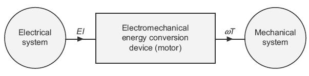
Fig. 11.32 Motor
11.15 WORKING PRINCIPLE OF DC MOTORS
The operation of a DC motor is based on the principle that when a current carrying conductor is placed in a magnetic field, a mechanical force is experienced by it. The direction of this force is determined by Fleming’s left-hand rule and its magnitude is given by the relation:
F = Bil Newton
For simplicity, consider only one coil of the armature placed in the magnetic field produced by a bipolar machine (see Fig. 11.33(a)). When DC supply is connected to the coil, current flows through it that sets up its own field, as shown in Figure 11.33(b). By the interaction of the two fields (i.e., field produced by the main poles and the coil), a resultant field is set up, as shown in Figure 11.33(c). The tendency of this is to come to its original position, that is, in straight line due to which force is exerted on the two coil sides and torque is produced; this torque rotates the coil.
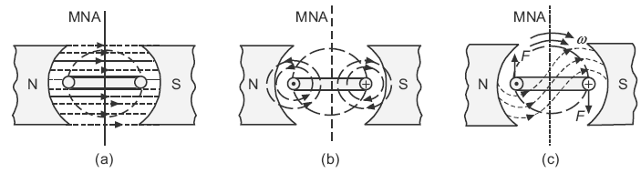
Fig. 11.33 (a) Field produced by main poles (b) Field produced by current carrying coil (c) Resultant field and direction of force exerted on conductors
Alternately, it can be said that the main poles produce a field Fm. Its direction is marked in Figure 11.34. When current is supplied to the coil (armature conductors), it produces its own field marked as Fr. This field tries to come in line with the main field and an electromagnetic torque is developed in the clockwise direction, as shown in Figure 11.35.
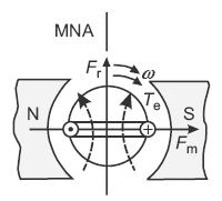
Fig. 11.34 Position of main field and rotor field, torque development by the alignment of two fields
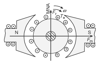
Fig. 11.35 Torque development in actual motor
In actual machine, a large number of conductors are placed on the armature. All the conductors placed under the influence of one pole (say North pole) carry the current in one direction (outward). While the other conductors placed under the influence of other pole, that is South pole, carry the current in opposite direction, as shown in Figure 11.35. A resultant rotor field is produced. Its direction is marked by the arrow arrowhead Fr. This rotor field Fr tries to come in line with the main field Fm and torque (Te) is developed. Thus, rotor rotates. It can be seen that to obtain a continuous torque, the direction of flow of current in each conductor or coil side must be reversed when it passes through the magnetic neutral axis (MNA). This is achieved with the help of a commutator.
Leave a Reply