The circuit containing a pure resistance of R Ω is shown in Figure 7.1. Let the alternating voltage applied across the circuit be given by the equation;
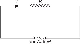
Fig. 7.1 Circuit containing resistance only
ν = Vm sin ω t (7.1)
Then, the instantaneous value of current flowing through the resistor will be;
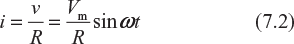
The value of current will be maximum when
ω t = 90° or sin ω t = 1
Im = Vm/R
Substituting this value in equation (7.2), we get
i = Im sin ω t (7.3)
7.2.1 Phase Angle
From Equations (7.1) and (7.3), it is clear that there is no phase difference between the applied voltage and the current flowing through pure resistive circuit, that is, phase angle between the voltage and the current is zero. The phasor diagram and wave diagram are shown in Figure 7.2(a) and (b), respectively.
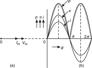
Fig. 7.2 (a) Phasor diagram (b) Wave diagram for voltage, current and power
Hence, in an AC circuit containing pure resistance, current is in phase with the voltage.
7.2.2 Power
Instantaneous power, p = vi = (Vm sin ω t) (Im sin ω t)
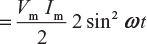
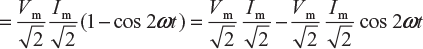
Average power consumed in the circuit over a complete cycle:
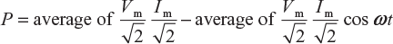
or
P = Vrms Irms − 0 or P = VI
7.2.3 Power Curve
Figure 7.2(b) shows the power curve for a pure resistive circuit. Points on the power curve are obtained from the product of the corresponding instantaneous values of voltage and current.
Leave a Reply