Before applying this method for the solution of parallel AC circuits, the reader should be familiar with the following important terms:
7.19.1 Admittance
The reciprocal of impedance of an AC circuit is called admittance of the circuit. Since impedance is the total opposition to the flow of AC in an AC circuit, the admittance is the effective ability of the circuit due to which it allows the AC to flow through it. It is represented by letter ‘Y‘.
Now,
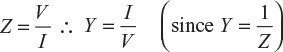
The unit of admittance is mho (i.e., ohm spelled backward and its symbol is Ʊ).
7.19.2 Admittance Triangle
Admittance can also be represented by a triangle similar to that of impedance.
Impedance Z of the circuit has two rectangular components resistance R and reactance X. Similarly, admittance Y also has two rectangular components conductance g and susceptance b, as shown in Figure 7.57.

Fig. 7.57 (a) Admittance triangle for inductive circuit (b) Admittance triangle for capacitive circuit
7.19.3 Conductance
The base of an admittance triangle is representing conductanceas shown in Figure 7.57.
Conductance,
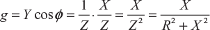
Conductance is always positive irrespective of the circuit parameters. The unit of conductance is mho.
7.19.4 Susceptance
The perpendicular or an admittance triangle is representing susceptance, as shown in Figure 7.57.
Susceptance,
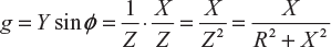
Susceptance is positive for capacitive reactance (see Fig. 7.57(b)) and negative for inductive reactance (see Fig. 7.57(a)). The unit of susceptance is mho.
7.19.5 Solution of Parallel AC Circuits by Admittance Method
Consider a parallel AC circuit shown in Figure 7.58. For its solution, we shall proceed as follows:
Step I: Draw the circuit as per the given problem as shown in Figure 7.58.
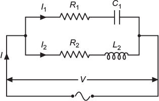
Fig. 7.58 AC circuits connected in parallel
Step II: Find impedance and phase angle of each branch.
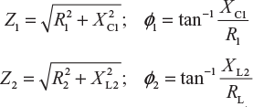
Step III: Find conductance, susceptance, and admittance of each branch.
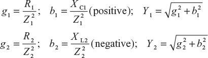
Step IV: Find the algebraic sum of conductance and susceptance.
G = g1 + g2; B = b1 − b2
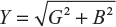
Step V: Find total admittance of the circuit.
Step VI: Find branch currents and total current.
I1 = VY1; I2 = VY2; I = VY
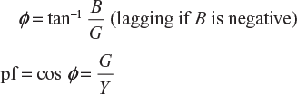
Step VII: Find the phase angle and the pf of the whole circuit.
Example 7.38
The active and lagging reactive components of current taken by an AC circuit from a 250−V supply are 50 A and 25 A, respectively. Calculate the conductance, susceptance, admittance, and power factor of the circuit.
(U.P.T.U. Tut.)
Active component of current, Ia = I cos ɸ = 50 A
Leading reactive component of current, Ir= I sin ɸ = 25
Circuit current, ![]()
Admittance of the circuit, ![]()
Power factor of the circuit, ![]()
Conductance of the circuit, G = Y cos ɸ = 0.223 × 0.8944 = 0.2 mho
Susceptance of the circuit, ![]()
= 0.1 mho (inductive)
Example 7.39
A parallel circuit has two branches. One branch contains a resistance of 8 Ω and inductance of 19.1 mH in series and the other contains a resistance of 6 Ω and capacitor of capacitance 601.55 F in series. This parallel circuit is connected across a supply voltage of 240 V, 50 Hz. Determine (i) current drawn by each branch, (ii) total current drawn from the mains, and (iii) pf of the whole circuit.
Solution:
The circuit is shown in Figure 7.59.
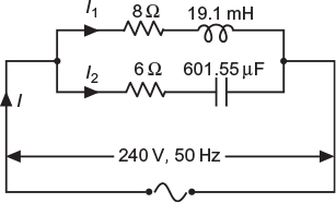
Fig. 7.59 Circuit as per data
Branch I
XL1 = 2 ɸ f L1 = 2 p × 50 × 0.0191 = 6 Ω

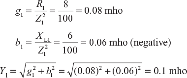
I1 = VY1 = 240 × 0.1 = 24 A
Branch II
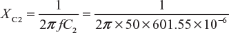
= 5.291 Ω
∴
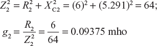
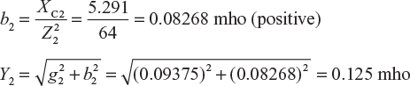
I2 = VY2 = 240 × 0.125 = 30 A
Total conductance, G = g1 + g2 = 0.08 + 0.09375 = 0.17375 mho
Total susceptance, B = − b1 + b2 = −0.06 + 0.08268 = 0.02268 mho (positive)
Total admittance, ![]()
Total current, I = VY = 240 × 0.1752 = 42.05 A
Power factor, cos ɸ = G/Y = 0.17375/0.1752 = 0.9917 leading
Example 7.40
Calculate the impedance and admittance of the Branch AB and CD of the circuit shown in Figure 7.60. Further, find the resistant impedance and admittance of the circuit.
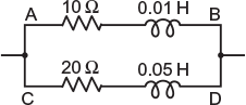
Fig. 7.60 Give circuit
Solution:
Branch AB
R1 = 10 Ω; L1 = 0.01 H
Inductive reactance, XL1 = 2 π f L1 = 2π × 50 × 0.01 = 3.1416 Ω
Impedance, ![]()
Conductance, 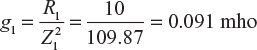
Susceptance, 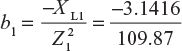 = −0.0286 mho (negative, being inductive)
Admittance, ![]()
Branch CD
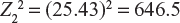
R2 = 20 Ω; L2 = 0.05 H; XL2 = 2π f L2 = 2π × 50 × 0.05 = 15.7 Ω
Impedance, ![]()
Conductance, 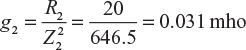
Susceptance,  −0.0243 mho (negative, being inductive)
Total conductance, G = g1 + g2 = 0.091 + 0.031 = 0.122 mho
Total susceptance, B = b1 + b2 = −0.086 − 0.0243 = −0.0529 mho
Total admittance, ![]()
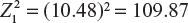
Impedance of the whole circuit, ![]()
Leave a Reply