In the field of engineering, various types of quantities such as physical, chemical, mechanical, thermal, and electrical are involved. For records, these quantities are required to be measured by different methods using different types of instruments. Electrical measuring instruments are widely used in the modern engineering world because of their accuracy, convenience, and reliability. These instruments are not only used to measure the electrical quantities but are also used to measure other non-electrical quantities such as temperature, strain, deformation, velocity, and pressure with the help of transducers. Thus, all the engineering students must be in acquaintance with these instruments. In this chapter, we shall focus our attention on construction and working principles of some of the important electrical instruments such as ammeter, voltmeter, wattmeter, and energy meter.
9.2 CONCEPT OF MEASUREMENTS
To measure the magnitude of a quantity, a fixed quantity of that kind is taken as basis, and then, whole quantity is compared with it. The fixed quantity that is taken as basis is called unit and the process of comparing the quantity with this unit is termed as measurement. In other words, measurement means recording of the magnitude of given quantity in terms of its base units, for example, length of a given object (say a rod) is measured as x metre, where x is the magnitude and metre is the unit that represents a standard length as accepted by Bureau of International Standards. The process of comparing the given quantity with fixed unit (or standard) is called measurements.
9.3 INSTRUMENTS AND THEIR CLASSIFICATION
A device used to measure some quantity is known as instrument. An instrument is used to determine the magnitude of given quantity. Broadly, instruments may be classified as mechanical, electrical, and electronic instruments.
9.3.1 Electrical Instruments
In electrical system, there are various electrical quantities, such as current, voltage, power, energy, frequency, power factor, resistance, inductance, and capacitance that are required to be measured. To measure these quantities, various instruments such as ammeter, voltmeter, wattmeter, energy meter, frequency meter, power factor meter, and ohm meter (or RLC meter) are used, respectively. These instruments are known as electrical instruments.
The instruments, such as ammeter, voltmeter, energy meter, and megger, are used to measure electrical quantities are called electrical instruments.
Classification of electrical instruments
The electrical instruments may be broadly classified as follows:
- Absolute instruments: The instruments that give the value of the quantity to be measured in terms of constants of the instrument are called absolute instruments. Such instruments do not require any previous calibration. The common example of this type of instrument is tangent galvanometer. The tangent galvanometer gives the value of current in terms of the tangent of deflection produced by the current, the radius, and number of turns of wire and the horizontal component of earth’s field. These instruments are seldom used except in standard laboratories for standardising the instruments.
- Secondary instruments: The instruments that determine the electrical quantity to be measured directly in terms of deflection are called secondary instruments. Such instruments are calibrated with standard instruments that have already been calibrated before using them. These instruments are generally used in practical life. The secondary instruments are further classified as follows:
- Indicating instruments: The instruments that indicate the magnitude of electrical quantity being measured instantaneously are called indicating instruments.
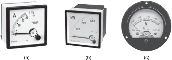 Fig. 9.1 Indicating instruments (a) Ammeter (b) Voltmeter (c) WattmeterIn such instruments, a pointer moves over the calibrated scale to indicate the magnitude of electrical quantity being measured. Ordinary ammeters, voltmeters, and watt-meters fall into this category (Fig. 9.1).
 - Integrating instruments: The instruments that add up the electrical quantity, that is, electrical energy and measure the total energy (in kWh) in a given period are called integrating instruments.
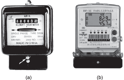 Fig. 9.2 Integrating instruments (a) Induction type energy meter (b) Digital energy meterIn such instruments, there are sets of dials or gears that register the total quantity of electricity or the total amount of electrical energy supplied to a circuit in a given period. The energy meters fall into this category (Fig. 9.2).
 - Recording instruments: The instruments that give a continuous record of the variations of the electrical quantity being measured are called recording instruments. These instruments more or less are the indicating instruments; however, in this case, the moving system carries an inked pen that rests slightly on a chart or graph wrapped over a drum moving at a uniform slow speed (Fig. 9.3). The motion of the drum is in a direction perpendicular to that of the deflection of the pen. The path traced out indicates the variations in the electrical quantity being measured during the given period. These instruments are used when we want to preserve the information that could be obtained later on. A simple example of these instruments is load curve plotter placed at the generating stations to plot variation of load at the generating station with respect to time. The other example is Electrocardiograph (ECG) that records the heart beats and shows the circulation of blood or effectiveness of heart (i.e., pumping system) to diagnose heart disease.
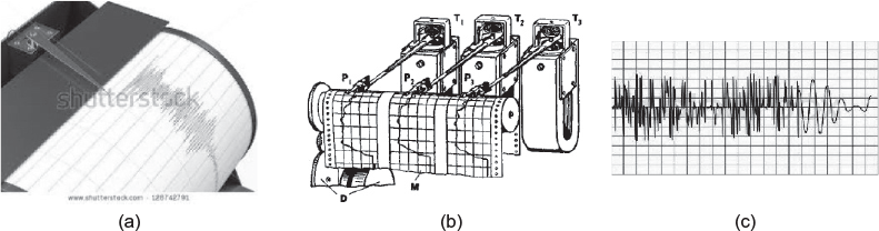 Fig. 9.3 Recording instruments (a) Paper wrapped over a drum (b) Inked pen tracing a graph (c) Graph traced on a paper
- Indicating instruments: The instruments that indicate the magnitude of electrical quantity being measured instantaneously are called indicating instruments.
Effects utilised in electrical instruments to produce deflecting torque
The principle of operation of electrical instruments depends upon various effects produced by electric current and voltage. The various effects and the electrical instruments in which these effects are utilised for their operation are mentioned in Table 9.1.
Table 9.1 Effects Utilized in Various Electrical Instruments
| Effect produced | Instruments in which this effect is generally utilised |
|---|---|
| (1) Magnetic effect | Ammeters and voltmeters |
| (2) Electrodynamic effect | Ammeters, voltmeters, and wattmeters, usually wattmeters. |
| (3) Electromagnetic induction effect | Ammeters, voltmeters, wattmeters and energy meters. Usually wattmeters and energy meters. |
| (4) Electrostatic effect | Voltmeters only |
| (5) Heating or thermal effect | Ammeters and voltmeters |
| (6) Chemical effect | DC ampere-hour meters |
Essentials of indicating instruments
In indicating instruments, a pointer moves over the calibrated scale to indicate the magnitude of electrical quantity being measured. The pointer is attached to a moving system pivoted in jewelled bearings. The forces or torques required for satisfactory operation of indicating instruments are as follows:
- Deflecting torque: The deflecting or operating torque (Td) is produced by making use of any one of the effects such as magnetic, electrodynamic, and electromagnetic induction. The actual method of torque production depends upon the type of instrument. The deflecting torque is required to move the moving system (and hence, the pointer attached to it) from zero position when the instrument is connected in the circuit to measure the electrical quantity.The torque produced by any of the abovementioned effects due to which moving system moves (or pointer deflects) from its zero position in an indicating instrument is called deflecting torque.
- Controlling torque: The controlling or restoring torque (Tc) opposes the deflecting torque and increases with the deflection of the moving system. The pointer is brought to rest at a position where the two opposing torques (i.e., deflecting torque and controlling torque) are equal. Thus, it ensures that the deflection of the pointer is according to the magnitude of electrical quantity being measured. If this torque was not provided, the pointer would continue to move indefinitely and the deflection shall be independent of the value of electrical quantity being measured.The other function of the controlling torque is to bring the pointer back to zero when the instrument is removed from the circuit or when the deflecting torque acting in the instrument is removed. If this torque was not provided, the pointer once deflected would not return to zero position on removing the deflecting torque. This torque is either obtained by a spring or by gravity in the indicating instruments.Thus, in indicating instruments, the torque that brings the pointer to zero position when the instrument is disconnected from the circuit or the torque that allows the pointer to deflect in accordance to the magnitude of electrical quantity is called controlling torque. It always opposes the deflecting torque.In spring control, one or two phosphor bronze spiral hair-springs are attached to the moving spindle. The other ends of the springs are attached to the fixed body or frame. In this case, the controlling torque (Tc) is directly proportional to the angle of deflection (θ ), that is, Tc ∞ θ.In gravity control, a small adjustable weight is attached to the moving system in such a way that due to gravity, it tries to bring the pointer to zero position when it is deflected. In this case, the controlling torque (Tc) is proportional to the sine of angle of deflection (θ ), i.e., Tc ∞ sinθ.
- Damping torque: When deflecting torque is applied to the moving system, it deflects the pointer. While the controlling torque controls the deflection and tries to stop the pointer at its final position, say at F, as shown in Figure 9.4, where deflection torque is equal to controlling torque (i.e., Td = Tc). However, due to inertia, the pointer oscillates around its final position F before coming to rest. These oscillations are undesirable because it causes delay in taking the reading. Then what to do? In order to avoid these oscillations and to bring the pointer quickly to its final deflected position, damping torque is provided. The damping torque opposes the movement (forward or backward) of the pointer and operates only when the system is moving. In fact, damping torque acts like a brake on the moving system.Thus, in indicating instruments, the torque that suppresses the undue oscillations of the pointer and brings the pointer to its final position quickly is called damping torque. It always acts opposite to motion.
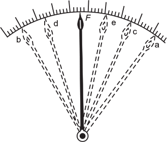 Fig. 9.4 Oscillating pointer
- Underdamping: When the damping torque provided in an indicating instrument is such that the pointer oscillates around its final position for long period, the instrument is called underdamped and the condition is referred to underdamping (Fig. 9.5). It delays in taking the reading.
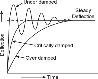 Fig. 9.5 Graphical representation of damping torque
 - Overdamping: When the damping torque provided in an indicating instrument is such that the pointer rises slowly and takes sufficient time to reach its final position, the instrument is called overdamped and the condition is referred to overdamping (Fig. 9.5). It makes the instrument sluggish.
- Critical damping: When the damping torque provided in an indicating instrument is such that the pointer rises quickly and obtains its final position immediately, the instrument is called critically damped and the condition is referred to critical damping (Fig. 9.5). This is what we require in indicating instruments.
- Underdamping: When the damping torque provided in an indicating instrument is such that the pointer oscillates around its final position for long period, the instrument is called underdamped and the condition is referred to underdamping (Fig. 9.5). It delays in taking the reading.
Leave a Reply