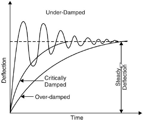
To obtain critical damping (i.e., the value of damping that is sufficient to enable the point to rise quickly to its deflected position without overshooting), adjustments are made while designing the instruments. Damping torque or force can be provided by the following methods.
9.5.1 Air Friction Damping
Two methods of air friction damping are illustrated in Figure 9.8(a) and (b). In the first case, a light aluminium piston, and in the second case, a vane is attached to the moving system. The piston (or vane) attached to the spindle moves in an air chamber, having cross-section either circular or rectangular, closed at one end.
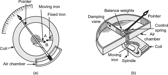
Fig. 9.8 Air friction damping (a) Air friction damping due to movement of piston in a cylinder (b) Air friction damping due to movement of vane in a chamber
The clearance between the piston and the sides of the chamber should be very small and uniform. When the pointer is deflected upscale to read the quantity to be measured, the piston moves out of the chamber, so that the pressure in the closed space S falls. The pressure on the open side of the piston is greater than the closed space that opposes the motion. Thus, the arrangement restricts the quick movement of the pointer and does not allow it to overshoot from its final position. However, if the pointer overshoots slightly, it has to come back. In this case, the piston is pushed into the air chamber compressing the air in the closed space S. This increases the pressure in the closed space that restricts the movement of the piston, and thus, opposes the rapid downward movement of the pointer. Hence, the necessary damping is produced and pointer comes to rest at its final position quickly.
9.5.2 Fluid Friction Damping
In this method of damping, light disc or vanes are attached to the spindle of the moving system and dipped into a pot of damping oil as shown in Figure 9.9(a) and (b). The motion of the moving system is always opposed by the friction of the damping oil on the vanes. The damping force acting on the vanes increases with the increase in the speed of the moving system. The damping force always acts in opposite direction to that of rotation and is zero when the vanes are stationary.
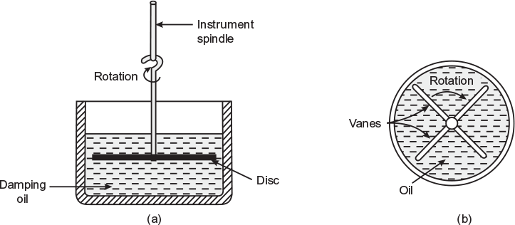
Fig. 9.9 Fluid friction damping (a) Side view (b) Top view
In this method of damping, no care is required as in the air friction damping. However, this method is not suitable for portable instruments because of oil contained in the instrument may leak through it. The other disadvantages of this method are creeping of oil and the necessity of using the instrument always in the vertical position.
9.5.3 Eddy Current Damping
In this method of damping, when the sheet of conducting but non-magnetic material such as copper or aluminium moves in a magnetic field so as to cut through magnetic lines of force, eddy currents are induced in the sheet and a force exists between these currents and the magnetic field. This force always acts in opposite direction to that of the cause producing it, that is, motion, according to Lenz’s law. This provides necessary damping torque. The magnitude of damping torque is directly proportional to the speed of the moving system.
Two methods of eddy current damping are shown in Figure 9.10. In Figure 9.10, a thin aluminium disc, mounted on the spindle carrying the pointer of the instrument, is allowed to rotate in the air gap of a damping magnet (permanent); when the spindle rotates, disc cuts through the magnetic lines of force and eddy currents are induced in it. Thus, a force acts on the disc that opposes the motion and provides the necessary damping torque.
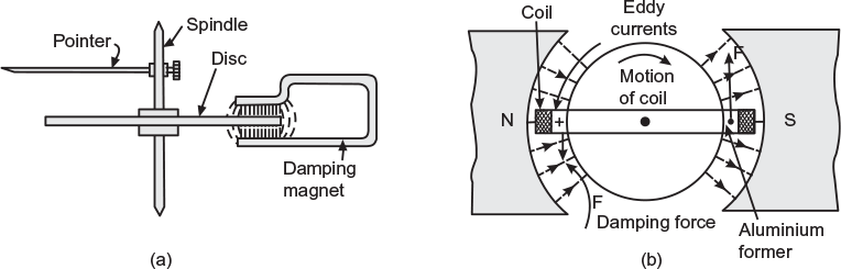
Fig. 9.10 Eddy-current damping (a) Eddy-current damping for disc (b) Eddy-current damping in an aluminium former
Figure 9.10(b) shows the 1eddy current damping employed in permanent-magnet moving coil instruments. The operating coil (coil that produces deflecting torque) is wound on a thin light aluminium former to which pointer is attached. When the coil wound on the former moves in the field of the permanent magnet, eddy currents are induced in the aluminium former. Thus, a force acts on the former that opposes the motion and provides the necessary damping.
Differentiation of indicating and integrating instruments is given in Table 9.2.
Table 9.2 Difference Between Indicating and Integrating Instruments
| S.No. | Indicating instruments | Integrating instruments |
|---|---|---|
| 1 | These instruments indicate the magnitude of electrical quantity being measured instantaneously. | These instruments add up the electrical quantity and measure the total quantity in a given period. |
| 2 | Controlling torque is provided in these instruments. | No controlling torque is provided in these instruments. |
| 3 | These instruments are equipped with damping torque. | In these instruments, damping torque is not required. |
| 4 | In these instruments, registering mechanism is not required. | In these instruments, registering mechanism is provided. |
Example 9.1
It is found that 10 A current passes through a resistor of 10 Ω value. The resistor has 5% tolerance. The error in measurement of current can be as high as 5%. What is the maximum error in the measurement of power calculated from the measured value of current and the nominal value of resistor?
(U.P.T.U. Tut.)
Solution:
Power dissipated in the resistor P = I2R
The limiting error in power dissipation = 2 × 5 + 5 = 15%
Hence, power dissipation, P = I2R = 102 × 10 = 1000 W ± 15%, that is, 1000 ± 150 W
Thus, the maximum error that crop-up during measuring power while calculated from the measured value of current and nominal value of resistor is ± 150 W.
Leave a Reply