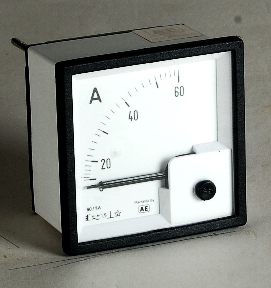
These instruments are very sensitive and accurate. These can be used only on DC as voltmeter and ammeter. The pictorial view of a voltmeter and ammeter is shown in Figures 9.19 and 9.20, respectively. The scale of such instruments is uniform, as shown in the Figure 9.20.
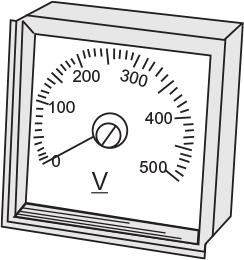
Fig. 9.19 Voltmeter
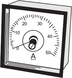
Fig. 9.20 Ammeter
9.9.1 Principle
The basic principle of permanent magnet-type moving coil instrument is that when a current-carrying conductor is placed in a magnetic field, a mechanical force is exerted on the conductor, as shown in Figure 9.21. The basic principle can also be stated that when a field Fr produced by the movable current-carrying coil tries to come in line with the main field Fm, a deflecting torque is developed as shown in Figure 9.22. Due to the production of deflecting torque, the pointer deflects over the scale.
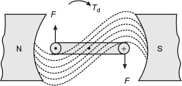
Fig. 9.21 Force exerted on a current carrying conductor placed in magnetic field
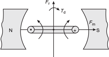
Fig. 9.22 Torque development by the alignment of two fields
9.9.2 Construction
The simple view of permanent magnet-type moving coil instrument is shown in Figure 9.23. It consists of a powerful permanent shoe magnet, a light rectangular coil of many turns of fine wire wound on a light aluminium former and a cylindrical iron core (a stationary part) inserted in between the coil sides to reduce reluctance for the magnetic lines of force. The coil is mounted on the spindle and acts as the moving element. Two phosphor bronze spiral hair springs are attached to the spindle. The springs provide the controlling torque as well as they act as incoming and outgoing leads for the current. Eddy current damping is provided by the aluminium former over which the operating coil is wound.
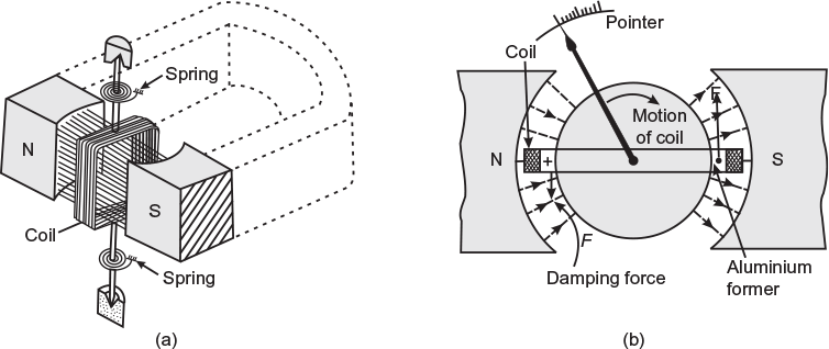
Fig. 9.23 (a) Parts of PMMC Instrument (b) Eddy current damping in PMMC instrument
9.9.3 Working
When the instrument is connected in the circuit, a current flows through the operating coil mounted on the spindle. Since the coil is placed in the strong magnetic field of permanent magnets, a force is exerted on the current-carrying conductors of the coil that produces deflecting torque. Thus, the pointer attached to the spindle deflects over the calibrated scale.
If current in the coil is reversed, the direction of deflecting torque will also be reversed because field produced by the permanent magnets does not change. This will give an opposite direction of rotation. Thus, the instrument cannot be used on AC, and it can only be used on DC.
9.9.4 Deflecting Torque
The deflecting torque Td depends upon the force acting on the coil sides.
Let
B = flux density in tesla in the air gap;
l = effective length of each coil side in metre;
N = number of turns of the coil;
r = distance in metre between centre of the coil and force;
I = current flowing through the coil in ampere;
Force acting on each coil side,
F = BIlN N
Deflecting torque,
Td = 2Fr = 2BIlNr Nm
Since all other quantities are constant, except I
∴
Td ∝ I
The controlling torque is provided by the springs
∴
Tc ∝ θ (where θ is angle of deflection)
At steady position of deflection,
Tc = Td;
∴
θ ∝ I
Since deflection θ is proportional to the operating current flowing through the coil, and therefore, the scale of such instruments is uniform.
9.9.5 Advantages and Disadvantages of Permanent Magnet Moving Coil Instruments
Advantages
- These instruments have uniform scale.
- Very effective; the reliable eddy current damping is provided.
- No hysteresis loss, as the former is of aluminium.
- Low power consumption because driving power is small.
- No effect of stray magnetic field, as working field provided by the permanent magnets is very strong.
- High torque or weight ratio, and therefore, such instruments require small operating current and are very sensitive.
- These instruments are very accurate and reliable.
Disadvantages
- These instruments cannot be used for AC measurements.
- These are costlier in comparison to moving iron instruments.
- Friction and temperature might introduce some error.
- Some errors are also caused due to ageing of control springs and permanent magnets.
9.9.6 Errors in Permanent Magnet Moving Coil Instruments
The main sources of errors in these instruments are due to the following:
- Weakening of stiffness of springs due to ageing and rise in temperature.
- Weakening of field produced by permanent magnet due to ageing and temperature effects.
- Change in resistance of the moving coil with temperature.
However, these errors are negligibly small and as such these instruments are considered to be most accurate for measuring currents and voltages in DC circuits.
9.9.7 Range
DC Ammeters
- Without shunt (i.e., instrument alone) 0–5 μA to 0 50 μA
- Without internal shunts up to 0–200 A
- With external shunts, up to 0–5000 A
DC Voltmeters
- Without series resistance or multiplier (i.e., instrument alone) 0–50 mV
- With series resistance, up to 0–3,000 V
Example 9.5
In a moving coil instrument, the moving coil consists of 300 turns wound on a former of dimension 3 cm × 2 cm. The flux density in the air gap is 0.05 T. Determine the turning moment on the coil when carrying a current of 10 mA.
Solution:
Deflecting force, F = BIlN
where
N = 300; l = 0.03 m; B = 0.05 T;
I = 10 × 10–3 A; r = 2/2 = 1 cm = 0.01 m
∴
F = 0.05 × 10 × 10–3 × 0.03 × 300 = 4.5 × 10⁻³ N
Turning moment on the coil, Td = 2F × r = 2 × 4.5 × 10–3 × 0.01
= 9 × 10⁻⁵ Nm
Example 9.6
In a moving coil instrument, the moving coil consists of 100 turns wound on a square former of length 3 cm. The flux density in the air gap is 0.06 T. Calculate the turning moment acting on the coil when carrying a current of 12 mA.
(U.P.T.U.)
Solution:
Number of turns on the coil, N = 100
Length of former, l = 3 cm = 0.03 m
Width of former, W = 3 cm = 0.03 m
Radius for the turning, ![]()
Field strength, B = 0.06 T
Current flowing through the coil, i = 12 mA = 0.012 A
Turning moment or deflecting torque, Td = 2 Bil N × r
= 2 × 0.06 × 0.012 × 0.03 × 100 × 0.015
= 6.48 × 10⁻⁵ Nm
A moving coil comprises 100 turns of insulate copper wire wound on a former of length 3 cm and breadth 4 cm. The resistance of the coil is 2,000 Ω. The field strength of the magnets is 0.06 T. The torque exerted by the control spring is 0.02 × 10⁻⁴ kgm/degree. Estimate the deflection of the instrument when a voltage of 120 V is applied across it.
Solution:
Number of turns of the coil, N = 100
Mean length of the coil, l = 3 cm = 0.03 m
Radius of the coil, ![]()
Flux density, B = 0.06 T
Current through the coil, ![]()
Deflecting force, F = BIlN = 0.06 × 0.06 × 0.03 × 100 = 0.0108 N
Deflecting torque, Td = 2Fr = 2 × 0.0108 × 0.02 = 4.32 × 10⁻⁴ Nm
Controlling torque/degree = 0.02 × 10⁻⁴ kgm = 0.02 × 10–4 × 9.81 Nm
Tc/θ = 0.1962 × 10⁻⁴ Nm/degree
Now,
∴ Deflection,
Example 9.8
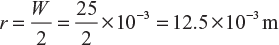
A moving coil instrument has the following data:
number of turns = 100; width of coil = 20 mm; depth of coil = 30 mm;
flux density in the gap = 0.1 Wb/m2
Calculate the deflecting torque when carrying a current of 10 mA. Further, calculate the deflection if the control spring constant is 2 × 10⁻⁶ Nm/degree.
Solution:
Here, N = 100; l = 30 mm = 0.03 m; ![]() = 10 mm = 0.01 m
= 10 mm = 0.01 m
B = 0.1 Wb/m2; I = 10 mA = 10 × 10–3 A
Tc/θ = 2 × 10⁻⁶ Nm/degree
Now,
F = BIlN = 0.1 × 10 × 10–3 × 0.03 × 100 = 3 × 10⁻³ N
Td = 2F × r = 2 × 3 × 10–3 × 0.01 = 0.06 × 10⁻³ Nm

∴ Deflection, 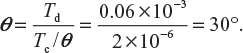
A moving coil millivoltmeter has a resistance of 200 Ω and the full-scale deflection is reached when a potential difference of 100 mV is applied across the terminals. The moving coil has effective dimensions of 30 mm × 25 mm and is wound with 100 turns. The flux density of the gap is 0.2 Wb/m2. Determine the control constant of the spring, if the final deflection is 100°.
(U.P.T.U.)
Solution:
Here, Rm = 200 Ω; V = 100 mV; l = 30 mm = 30 × 10–3 m;
N = 100; B = 0.2 Wb/m2; θ = 100°
Full-scale deflection current, ![]()
= 0.5 mA = 0.5 × 10⁻³ A
Deflecting torque, Td = 2 BilrN = 2 × 0.2 × 0.5 × 10–3 × 30 × 10–3 × 12.5 × 10–3 × 100
= 75 × 10–7 Nm
Full-scale deflection, θ = 100°
Control constant of spring = ![]()
9.10 DIFFERENCE BETWEEN AMMETER AND VOLTMETER
There is no fundamental difference in the operating principles of ammeters and voltmeters. Both are current operated devices (except electrostatic-type voltmeters), that is, deflecting torque is produced when current flows through their operating coils. In an ammeter, the deflecting torque is produced by current to be measured or by a definite fraction of it, whereas in a voltmeter, torque is produced by the current proportional to the voltage to be measured. Thus, the real difference between the two instruments is in the magnitude of the current producing the deflecting torque. The essential requirements of a measuring instrument are that its introduction into the circuit, where measurements are to be made, does not alter the circuit conditions and the power consumed by them for their operation should be very small.
An ammeter is connected in series with the circuit whose current is to be measured. Therefore, it should have a low resistance. On the other hand, a voltmeter is connected in parallel with the circuit whose voltage is to be measured, and therefore, it must have high resistance. Thus, we conclude that the difference is only in the resistance of the instrument; in fact, an ammeter can be converted into voltmeter by connecting a high resistance in series with it. Similarly, a voltmeter can be converted into an ammeter by connecting a shunt across the voltmeter.
Example 9.10
A meter has a full-scale angle of 90° at a current of 1 A. This meter has perfect square-law response. What is the current when the deflection angle is 45°? Draw the conclusion.
(U.P.T.U.)
Here, I1 = 1 A; θ1 = 90°, θ2 = 45°
Since,
θαI2,
∴

or
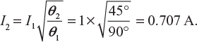
Learning outcome: The result shows that when deflection is reduced to half, the current flowing through the meter is not reduced to half, it is 70.7% of the previous value. In meters that follows the square law, the scale is not uniform.
Leave a Reply