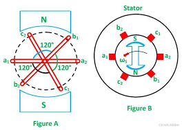
In a three-phase system, there are three equal voltages (or emfs) of the same frequency having a phase difference of 120°. These voltages can be produced by a three-phase, AC generator having three identical windings (or phases) displaced 120° electrical apart. When these windings are rotated in a stationary magnitude field (see Fig. 8.1(a)) or when these windings are kept stationary and the magnetic field is rotated (see Fig. 8.1(b)), an emfs is induced in each winding or phase. These emfs are of same magnitude and frequency, but are displaced from one another by 120° electrical.
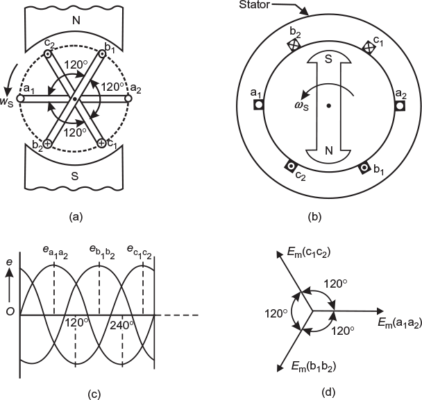
Fig. 8.1 (a) Coils rotating in stationary magnetic field (b) Magnetic field rotating in stationary coils (c) Wave diagram of induced emfs in three coils (d) Phasor diagram of induced emfs in three coils
Consider three identical coils a1a2, b1b2, and c1c2 mounted, as shown in Fig 8.1(a) and (b). Here, a1, b1, and c1 are the start terminals, while a2, b2, and c2 are the finish terminals of the three coils. It may be noted that a phase difference of 120° electrical is maintained between the corresponding start terminals a1, b1, and c1. Let the three coils mounted on the same axis be rotated (or the magnetic field system be rotated keeping coils stationary) in anticlockwise direction at ω radians/s, as shown in Figure 8.1(a) and (b), respectively.
Three emfs are induced in the three coils, respectively. Their magnitudes and directions, at this instant, are as follows:
- The emf induced in coil a1a2 is zero (consider start terminal a1) and is increasing in the positive direction, as shown by wave ea1a2 in Figure 8.1(c).
- Coil b1b2 is 120° (electrical) behind coil a1a2. The emf induced in this coil is negative and is becoming maximum negative (consider start terminal b1) as shown by eb1b2 in Figure 8.1(c).
- Coil c1c2 is 120° (electrical) behind b1b2 or 240° (electrical) behind a1a2. The emf induced in this coil is positive and is decreasing (consider start terminal c1) as shown by wave ec1c2 in Figure 8.1(c).
8.4.1 Phasor Diagram
The emfs induced in three coils are of the same magnitude and frequency, but are displaced by 120° (electrical) from each other as shown by phasor diagram in Figure 8.1(d). These can be represented by the equations:
ea1a2 = Em sin ωt; eb1b2 = Em sin(ωt − 2π /3); ec1c2 = Em sin(ωt − 4π /3) = Em sin(ω t − 240°)
Leave a Reply