The basic principle of a transformer is electromagnetic induction.
A simple form of a transformer is shown in Figure 10.3(a). It essentially consists of two separate windings placed over the laminated silicon steel core. The winding to which AC supply connected is called primary winding and the winding to which load connected is called a secondary winding.
When AC supply of voltage V1 is connected to primary winding, an alternating flux is set up in the core. This alternating flux when links with the secondary winding, an emf is induced in it called mutually induced emf. The direction of this induced emf is opposite to the applied voltage V1, according to Lenz’s law as shown in Figure 10.3(b).
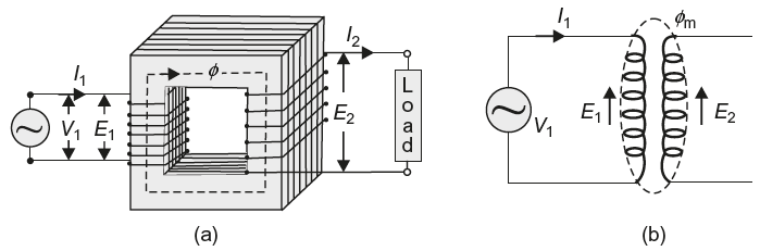
Fig. 10.3 (a) Simple diagram of a transformer (b) Mutual flux linking with primary and secondary winding
The same alternating flux also links with the primary winding and produces self-induced emf E1. This induced emf E1 also acts in opposite direction to the applied voltage V1 according to Lenz’s law and hence called ‘back emf’.
Although there is no electrical connection between primary and secondary winding, electrical power is transferred from primary circuit to secondary circuit through mutual flux.
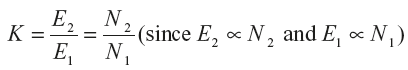
The induced emf in the primary and secondary winding depends upon the rate of change of flux linkages, that is,  . The rate of change of flux (dɸ/dt) is the same for both primary and secondary windings. Therefore, an induced emf in primary winding is proportional to number of turns of the primary winding (E1 ∝ N1), and in secondary winding, it is proportional to number of turns of the secondary winding (E2 ∝ N2).
∴ In case N2 > N1, the transformer is step-up transformer, and when N2 < N1, the transformer is step-down transformer.
Turn ratio: The ratio of primary to secondary turns is called turn ratio, that is, turn ratio = N2/N1.
Transformation ratio: The ratio of secondary voltage to primary voltage is called voltage transformation ratio of the transformer. It is represented by K.
Leave a Reply