To understand the theory, operation, and applications of a transformer, it is better to view a transformer first as an ideal device. For this, the following assumptions are made:
- Its coefficient of coupling (k) is unity.
- Its primary and secondary windings are pure inductors having infinitely large value.
- Its leakage flux and leakage inductances are zero.
- Its self- and mutual inductances are zero having no reactance or resistance.
- Its efficiency is 100 per cent having no loss due to resistance, hysteresis, or eddy current.
- Its transformation ratio (or turn ratio) is equal to the ratio of its secondary to primary terminal voltage and also as the ratio of its primary to secondary current.
- Its core has permeability (µ) of infinite value.
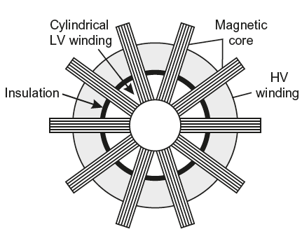
Fig. 10.10 Top view of berry-type transformer
Thus, an ideal transformer is one which has no ohmic resistance and no magnetic leakage flux, that is, all the flux produced in the core links with both primary and secondary. Hence, transformer has no copper losses and core losses. It means an ideal transformer consists of two purely inductive coils wound on a loss-free core. Although in actual practice, it is impossible to realize such a transformer, yet for convenience, it is better to start with an ideal transformer and then extend it to an actual transformer.
In an ideal transformer, there is no power loss, and therefore, output must be equal to input.
That is,
E2l2 cosɸ = E1I1 cosɸ or E2I2 = E1I2 or 
Since,
E2 ∝ N2; E1 ∝ N1 and E1 ≅ V1 ; E2 ≅ V2
Hence, primary and secondary currents are inversely proportional to their respective turns.
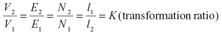
The ratio of secondary turns to primary turns is called transformation ratio of the transformer and is represented by K.
10.5.1 Behaviour and Phasor Diagram
Consider an ideal transformer whose secondary is open as shown in Figure 10.11(a). When its primary winding is connected to sinusoidal alternating voltage V1, a current Imag flows through it. Since the primary coil is purely inductive, the current Imag lags behind the applied voltage V1 by 90°. This current sets up alternating flux (or mutual flux ɸm) in the core and magnetizes it. Hence, it is called magnetizing current. Flux is in phase with Imag as shown in the phasor diagram and wave diagram in Figure 10.11(b) and (c), respectively. The alternating flux links with both primary and secondary windings. When it links with primary, it produces self-induced emf E1 in opposite direction to that of applied voltage V1. When it links with secondary winding, it produces mutually induced emf E2 in opposite direction to that of applied voltage. Both the emfs E1 and E2 are shown in phasor diagram (Fig. 10.11(b)).
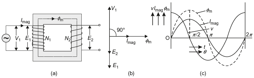
Fig. 10.11 Ideal transformer (a) General view (b) Phasor diagram (c) Wave diagram
A transformer is analogous to mechanical gear drive because of the facts given in Table 10.2.
Table 10.2 Comparison between Mechanical Gear Drive and Transformer
| S. No. | Mechanical Gear Drive | Transformer |
|---|---|---|
| 1. | It transfers mechanical power from one shaft to the other shaft. | It transfers electrical power from one circuit to the other. |
| 2. | There is perfect ratio between the number of teeth and the speeds of the two gears, i.e., whereT1 = No. of teeth of gear 1T2 = No. of teeth of gearN2 = Speed of gear 2N1 = Speed of gear 1 whereT1 = No. of teeth of gear 1T2 = No. of teeth of gearN2 = Speed of gear 2N1 = Speed of gear 1 | There is perfect ratio between the number of turns and the induced emf or current of the two windings, i.e.,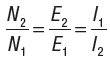 where N2 = No. of secondary turnsN1 = No. of primary turnsE2 = EMF in secondaryE1 = EMF is primaryI1 = Current in primaryI2 = Current in secondary where N2 = No. of secondary turnsN1 = No. of primary turnsE2 = EMF in secondaryE1 = EMF is primaryI1 = Current in primaryI2 = Current in secondary |
| 3. | Power is transferred through mechanical mesh. |
Leave a Reply