While drawing simplified circuit of a transformer, the exciting circuit (i.e., exciting resistance and exciting reactance) can be omitted.
The simplified equivalent circuit of a transformer is drawn by representing all the parameters of the transformer either on the secondary or on the primary side. The no-load current I0 is neglected as its value is very small as compared to full-load current, therefore, ![]() = I1
= I1
10.15.1 Equivalent Circuit When All the Quantities Are Referred to Secondary
The primary resistance when referred to secondary side, its value is ![]() = K2R1 and the total or equivalent resistance of transformer referred to secondary, Res = R2 +
= K2R1 and the total or equivalent resistance of transformer referred to secondary, Res = R2 + ![]() . Similarly, the primary reactance when referred to secondary side, its value is
. Similarly, the primary reactance when referred to secondary side, its value is ![]() = K2X1 and the total or equivalent reactance of transformer referred to secondary, Xes = X2 +
= K2X1 and the total or equivalent reactance of transformer referred to secondary, Xes = X2 + ![]() . All the quantities when referred to the secondary side are shown in Figure 10.25.
. All the quantities when referred to the secondary side are shown in Figure 10.25.
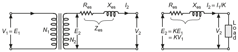
Fig. 10.25 (a) and (b) Simplified equivalent circuit of a loaded transformer when all quantities are referred to secondary side
Total or equivalent impedance referred to secondary side,
Zes= Res + jXes
There is some voltage drop in resistance and reactance of transformer referred to secondary. Hence,
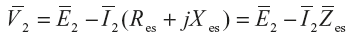
Phasor diagrams
The phasor (vector) diagrams of a loaded transformer when all the quantities are referred to secondary side for resistive, inductive, and capacitive loads are shown in Figure 10.26(a), 10.26(b), and 10.26(c), respectively. The voltage drops in resistances (vectors) are taken parallel to the current vector and the voltage drops in reactance (vectors) are taken quadrature to the current vector.
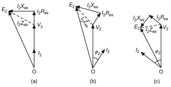
Fig. 10.26 Phasor diagram of a loaded transformer when all quantities are referred to secondary side (a) for resistive load (b) for inductive load (c) for capacitive load
10.15.2 Equivalent Circuit When All the Quantities Are Referred to Primary
In this case, to draw the equivalent circuit, all the quantities are to be referred to primary, as shown in Figure 10.27.
Fig. 10.27 (a) and (b) Simplified equivalent circuit of a loaded transformer when all quantities are referred to primary side
Secondary resistance referred to primary, ![]() = R2/K2
= R2/K2
Equivalent resistance referred to primary, Rep = R1+ ![]()
Secondary reactance referred to primary, ![]() = X1/K2
= X1/K2
Equivalent reactance referred to primary, Xep = X1 + ![]()
Total or equivalent impedance referred to primary side,
Zep= Rep + jXep
There is some voltage drop in resistance and reactance of the transformer referred to primary side. Therefore,
The phasor diagram to transformer when all the quantities are referred to primary side for different types of loads are shown in Figure 10.28.
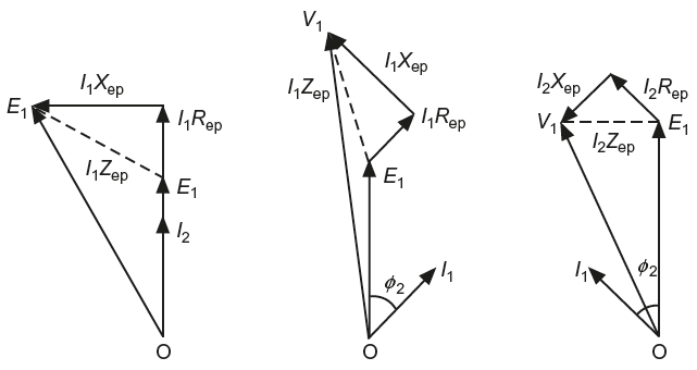
Fig. 10.28 Phasor diagram of a loaded transformer when all quantities are referred to primary side (a) for resistive load (b) for inductive load (c) for capacitive load
10.16 EXPRESSION FOR NO-LOAD SECONDARY VOLTAGE
For a loaded transformer, when all the quantities are referred to secondary side, its phasor diagram can be drawn as shown in Figure 10.29.
Complete the phasor diagram as shown in Figure 10.29. From the phasor diagram, we can derive the approximate and exact expressions for no-load secondary voltage.
10.16.1 Approximate Expression
- For lagging p.f. (inductive load), consider right-angled triangle OEC (Figure 10.29(a)). OC = OE = OA + AD + DE = OA + AD + BFor E2 = V2 + I2Res cosɸ2 + I2Xes sinɸ2
- For unity p.f. (resistive load), consider right-angled triangle OBC (Figure. 10.29(b)). OC ≅ OB = OA + AB; E2 = V2 + I2Res
- For leading p.f. (capacitive load), consider right-angled triangle OEC (Figure 10.29(c)). OC ≅ OE = OA + AD − DE = OA + AD − BFor E2 = V2 + I2Res cosɸ2 − I2Xes sinɸ2
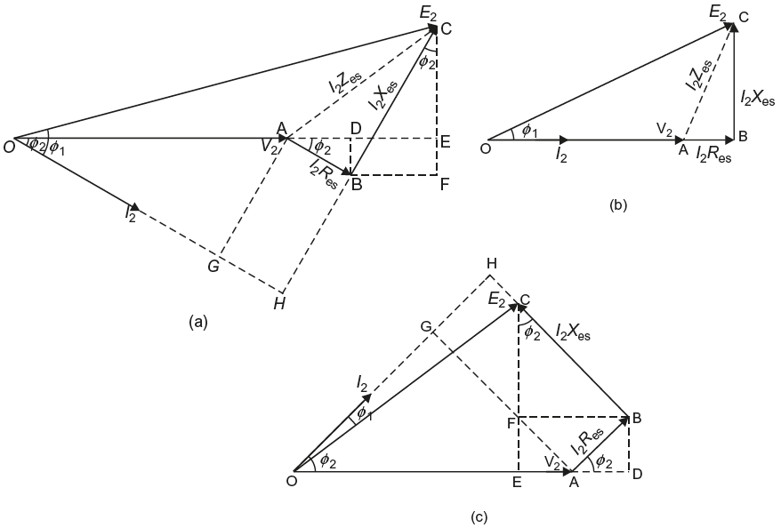
Fig. 10.29 Phasor diagram of a loaded transformer where V2 is taken as reference vector (a) for inductive load (b) for resistive load (c) for capacitive load
10.16.2 Exact Expression
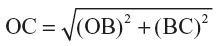
- For a lagging p.f. (inductive load), consider right-angled triangle OHC (Figure 10.29(a)).

 or
or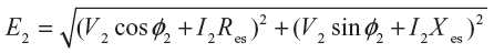 Primary p.f.,
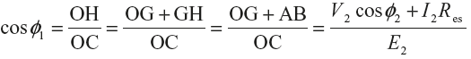
- For unity p.f., (resistive load), consider right-angled triangle OBC (Figure 10.29(b)).
 or
or Primary p.f.,
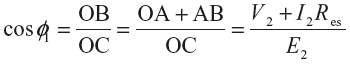
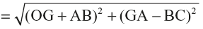
- For leading p.f. (capacitive load), consider right-angled triangle OHC (Figure 10.29(c)).

 or
or Primary p.f.,
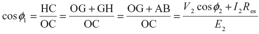
Leave a Reply