The approximate expression for the no-load secondary voltage is derived in Section 16.1.
For inductive load
E2 = V2 + I2Res cosɸ2 + I2Xes sinɸ2
or
E2 − V2 = I2Res cosɸ2 + I2Xes sinɸ2
or
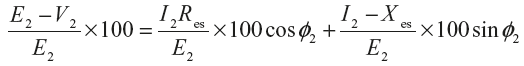
where,
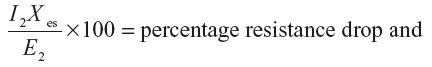
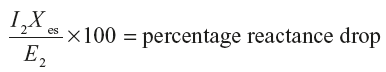
∴
% Reg = % resistance drop × cos ɸ2 + % reactance drop × sin ɸ2
Similarly
(ii) For resistive load: % Reg = % resistance drop
(iii) For capacitive load
∴
% Reg = % resistance drop × cos ɸ2 − % reactance drop × sin ɸ2
Example 10.17
A 10 kVA, 2000/400 V, single-phase transformer has resistance and leakage reactance as follows:
Primary winding: Resistance = 5.5 Ω Reactance = 12 Ω
Secondary winding: Resistance = 0.2 Ω, Reactance = 0.45 Ω
Determine the value of the secondary voltage at full load, 0.8 p.f. lagging, when the primary supply voltage is 2000 V.
Solution:
Transformer rating = 10 kVA = 10 × 103 VA
Primary induced voltage, E1 = 2000 V
Secondary induced voltage, E2 = 400 V
Primary resistance, R1 = 5.5 Ω; Primary reactance, X1 = 12 Ω
Secondary resistance, R2 = 0.2 Ω; Secondary reactance, X2 = 0.45 Ω
Load p.f.,
cos ɸ2 = 0.8 lagging
Transformation ratio,
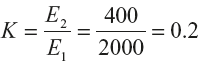
Primary resistance referred to secondary side,
![]() = K2R1 = (0.2)2 × 5.5 = 0.22Ω
= K2R1 = (0.2)2 × 5.5 = 0.22Ω
Equivalent resistance referred to secondary side,
Res = R2 + ![]() = 0.2 + 0.22 = 0.42Ω
= 0.2 + 0.22 = 0.42Ω
Primary reactance referred to secondary side,
![]() = K2X1 = (0.2)2 × 12 = 0.48Ω
= K2X1 = (0.2)2 × 12 = 0.48Ω
Equivalent reactance referred to secondary side,
Xes = X2 + ![]() = 0.45 + 0.48 = 0.93Ω
= 0.45 + 0.48 = 0.93Ω
Load p.f.,
cosɸ2 = 0.8 ∴ sinɸ2 = sincos−1 0.8 = 0.6
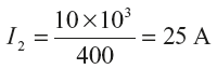
Full-load secondary current,
As the primary supply voltage,
V1 = E1 = 2000V
E2 = KE1 = 0.2 × 2000 = 400V
Using the expression;
E2 = V2 + I2Res cosɸ2 − I2Xes sinɸ2
Secondary terminal voltage,
V2 = E2 − I2Res cosɸ2 − I2Xes sinɸ2
= 400 − 25 × 0.42 × 0.8 − 25 × 0.93 × 0.6 = 400 − 8.4 − 13.95 = 377.65 A
Example 10.18
The ratio of turns of a single-phase transformer is 8, the resistance of the primary and the secondary windings are 0.85 Ω and 0.012 Ω, respectively, and the leakage reactance of these windings are 4.8 Ω and 0.07 Ω, respectively. Determine the voltage to be applied to the primary to obtain a current of 150 A in the secondary when the secondary terminal are short circuited. Ignore the magnetizing current.
Solution:
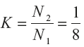
Ratio of turns,

Primary resistance,
R1 = 0.85;
Primary reactance,
X1 = 4.8Ω
Transformation ratio,
Secondary resistance
R2 = 0.012Ω
Secondary reactance,
X2 = 0.07Ω
Secondary resistance referred to primary, 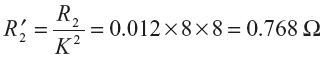
Equivalent resistance referred to primary, Rep = R1 + ![]() = 0.85 + 0.768 = 1.618Ω
= 0.85 + 0.768 = 1.618Ω
Secondary reactance referred to primary, 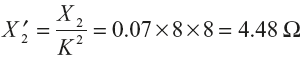
Equivalent reactance referred to primary, Xep = X1 + ![]() = 4.8 + 4.48 = 9.28Ω
= 4.8 + 4.48 = 9.28Ω
Equivalent impedance referred to primary, ![]()
= 9.42 Ω
Short circuit current referred to primary, I1(SC) = KI2(SC) = ![]() × 150 = 18.75 A
× 150 = 18.75 A
Voltage applied to the primary under short circuit condition,
V1(SC) = I1(SC) × Zep =18.75 × 9.42 = 176.625 V
Leave a Reply