- Single-phase and three-phase autotransformers are employed for obtaining variable output voltages at the output. When used as variable ratio autotransformers, these are known by their trade names, such as variac, dimmerstat, and autostat.A variable ratio autotransformer (or variac) has a toroidal core and toroidal winding. A sliding contact with the winding is made by carbon brush, as shown in Figure 10.36(b) and Figure 10.39. The position of the sliding contact can be varied by a hand wheel which changes output voltage. These are mostly used in laboratories.
- Autotransformers are also used as boosters for raising the voltage in an AC feeder.
- As furnace transformers, for getting a convenient supply to suit the furnace winding from normal 230 V AC supply
- Autotransformers with a number of tapings are used for starting induction motors and synchronous motors. When autotransformers are used for this purpose, these are known as autostarters.
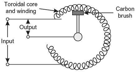
Fig. 10.39 Auto-transformer as a variac
Example 10.40
Determine the core area, the number of turn, and the position of the tapping point for a 500 kVA, 50 Hz single phase, 6600/5000 V autotransformer, assuming the following approximate values: emf per turn 8 V, maximum flux density 1.3 tesla.
Solution:
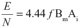
We know,
E = 4.44 f BmAiN
or
or
8 = 4.44 × 50 × 1.3 × Ai
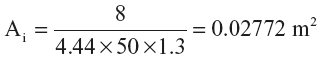
= 277.2 cm2
Turns on the primary side, 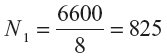
Turns on the secondary side 
Hence, tapping should be 200 turns from high-voltage end or 625 turns from the common end as shown in Figure 10.40.
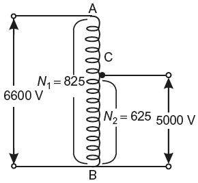
Fig. 10.40 Circuit as per data
Example 10.41
An autotransformer having 1500 turns is connected across a 500 V AC supply. What secondary voltage will be obtained if a tap is taken at 900th turn?
Solution:
Supply voltage,
V1 = 500 V
Total turns,
N1 = 1500
Secondary turns,
N2 = 900
Voltage per turn
Secondary voltage,
V2 = Voltage per turn × N2 = ![]() × 900 = 300 V
× 900 = 300 V
Example 10.42
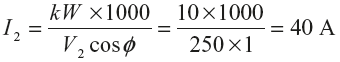
An autotransformer supplies a load of 10 kW at 250 V and at unity power factor. If the primary voltage is 500 V, then determine the following: (i) transformation ratio, (ii) secondary current, (iii) primary current, (iv) number of turns across secondary if total number of turns is 500, (v) power transformed, and (vi) power conducted directly from the supply mains to load.
Solution:
- Transformation ratio,
- Secondary current,
- Primary current, I1 = KI2 = 0.5 × 40 = 20A
- Turns across secondary, N2 = KN1 = 0.5 × 500 = 250
- Power transformed = Load × (I – K) = 10 (1 – 0.5) = 5kW
- Power conducted directly from supply mains = 10 – 5 = 5kW
A 400/100 V, 5 kVA, two-winding transformer is to be used as an autotransformer to supply power at 400 V from 500 V source. Draw the connection diagram and determine the kVA output of the autotransformer.
Solution:
For a two-winding transformer
V1I1 = kVA × 1000 or 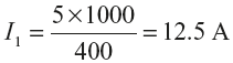
V2I2 = kVA × 1000 or 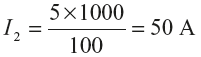
Figure 10.41 shows the use of two-winding transformer as an autotransformer to supply power at 400 V from a 500 V source.
Here, ![]() = 500 V,
= 500 V, ![]() =400 V
=400 V
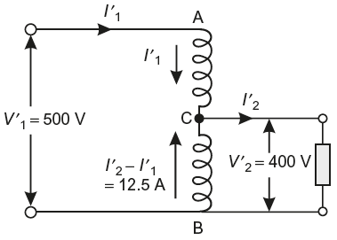
Fig. 10.41 Circuit as per data
Transformation ratio,
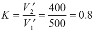
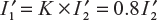
Current through 400 V winding,

Since the current rating of 400 V winding is 12.5 A
0.2 ![]() = 12.5 or
= 12.5 or 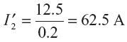
The kVA output of the autotransformer = 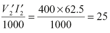
Example 10.44
The primary and secondary voltages of an autotransformer are 250 V and 200 V, respectively. Show with the aid of a diagram the current distribution in the windings when the secondary current is 100 A and calculate the economy of copper in this particular case (in percentage).
Solution:
Transformation voltage, 
Secondary load current, I2 = 100 A
Primary current, I1 = KI2 = 0.8 × 100 = 80 A
The current distribution is shown in Figure 10.42
Economy in copper = K = 0.8 or 80%
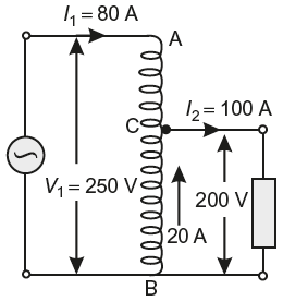
Fig. 10.42 Circuit as per data
Leave a Reply