The transformers are often classified according to their applications. Following are the important types of transformers:
- Power transformers: These transformers are used to step up the voltage at the generating station for transmission purposes and then to step down the voltage at the receiving stations. These transformers are of large capacity (generally above 500 kVA). These transformer usually operate at high average load, which would cause continuous capacity copper loss, thus affecting their efficiency. To have minimum losses during 24 h, such transformers are designed with low copper losses.
- Distribution transformers: These transformers are installed at the distribution substations to step down the voltage. These transformers are continuously energised causing the iron losses for all the 24 h, Generally, the load on these transformers fluctuate from no-load to full load during this period. To obtain high efficiency, such transformers are designed with low iron losses.
- Instrument transformers: To measure high voltages and currents in power system potential transformer (P.T.) and current transformer (C.T.) are used, respectively. The potential transformers are used to decrease the voltage, and current transformers are used to decrease the current up to measurable value. These are also used with protective devices.
- Testing transformers:These transformers are used to step up voltage to a very high value for carrying out the tests under high voltage, for example, for testing the dielectric strength of transformer oil.
- Special purpose transformer: The transformers may be designed to serve special purposes, and these may be used with furnaces, rectifiers, welding sets, etc.
- Autotransformers: These are single-winding transformers used to step down the voltages for starting of large three-phase squirrel cage induction motors.
- Isolation transformer: These transformers are used only to isolate (electrically) the electronic circuits from the main electrical lines, and therefore, their transformation ratios are usually one.
- Impedance matching transformer: These transformers are used at the output stage of the amplifier for impedance matching to obtain maximum output from the amplifiers.
10.31 POWER TRANSFORMER AND ITS AUXILIARIES
The transformers used in the power system for transfer of electric power or energy from one circuit to the other are called power transformers. The rating of a transformer includes voltage, frequency, and kVA. The kVA rating is the kVA output that a transformer can deliver at the rated voltage and frequency under general service conditions without exceeding the standard limit of temperature rise (usually 45° to 60°C). The power transformer has the following important parts:
- Magnetic circuit: The magnetic circuit comprises of transformer core. The transformer core may be core type or shell type in construction. The power transformers used in the power system are mostly three-phase transformers. In a core-type three-phase transformer core has three limbs of equal area of cross-section.
- Electrical circuit: In three-phase transformers, there are three primary (H.V.) windings and three secondary (L.V.) windings. Whole of the L.V. winding is wound over one limb next to the core, then whole of the H.V. winding is wound over the L.V. winding. In between the L.V. winding and H.V. winding and between core and L.V. winding, insulation is provided.
- Transformer oil: Transformer oil is a mineral oil obtained by fractional distillation of crude petroleum. The oil is used only in the oil-cooled transformers. The oil not only carries the heat produced due to losses in the transformer, by convection from the windings and core to the transformer tank, but also has even more important function of insulation.When transformer delivers power, heat is produced due to the iron and copper losses in the transformer. This heat must be dissipated effectively; otherwise, the temperature of the winding will increase. The raise in temperature further increases with the losses. Thus, the efficiency of the transformer will decrease. As there is no rotating part in the transformer, it is difficult to cool down the transformer as compared to rotating machines. Various methods are adopted to cool down the transformers of different rating. The common methods are air natural cooling, oil immersed natural cooling, oil immersed forced oil circulation natural cooling, oil immersed forced oil circulation with air blast cooling, oil immersed forced oil circulation with water cooling, etc.Generally, for cooling of distribution transformers, oil immersed natural cooling method is adopted. Cooling tubes or small cooling radiators are used with the main tanks, as shown in Figure 10.43, to increase the surface area for the dissipation of heat.
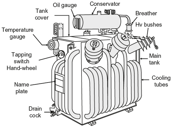 Fig. 10.43 Pictorial view of a 200 kVA, 11 kV/400 V oil-immersed natural cooled distribution transformer
 - Tank cover: A number of parts are arranged on the tank cover of which most important are as follows:
- Bushing: The internal winding of the transformer is connected to the lines through copper rods or bars which are insulated from the tank cover, these are known as bushings. Up to 33 kV, ordinary porcelain bushing can be used. Above this voltage, oil-filled bushings or condenser bushing are employed.
- Oil conservator tank: Oil conservator is also known as an oil expansion chamber. It is a small cylindrical air-tight and oil-tight vessel. The oil conservator is connected with a tube to the main transformer tank at the tank cover. This tank is partially filled with oil. The expansion and contraction of oil changes the oil level in the conservator.
- Breather: The transformer oil should not be allowed to come in contact with atmospheric air, since a small amount of moisture causes a great decrease in the dielectric strength of transformer oil. All the tank fittings are made air-tight. When oil level in the oil conservator changes, air moves in and out of the conservator. This action is known as breathing. The breathed air is made to pass through an apparatus called breather to abstract moisture. Breather contains silica gel or some other drying agent such as calcium chloride. This ensures that only dry air enters the transformer tank.
- Buchholz relay: This is installed in between the main tank and the oil conservator. It is a gas relay which gives warning of any fault developing inside the transformer, and if the fault is dangerous, the relay disconnects the transformer circuit. This relay is installed in the transformer having capacity more than 750 kVA.
All the important parts of a 200 kVA, 11 kV/400 V oil immersed natural cooled distribution transformer are shown in Figure 10.43.
Leave a Reply