
A three-phase induction motor consists of two main parts, namely stator and rotor.
- Stator: It is the stationary part of the motor. It has three main parts, namely outer frame, stator core, and stator winding.
- Outer frame: It is the outer body of the motor. Its function is to support the stator core and to protect the inner parts of the machine. For small machines, the fame is casted, but for large machines, it is fabricated.To place the motor on the foundation, feet are provided in the outer frame as shown in Figure 12.1.
- Stator core: The stator core is to carry the alternating magnetic field which produces hysteresis and eddy current losses; therefore, core is built up of high grade silicon steel stamping. The stampings are assembled under hydraulic pressure and are keyed to the frame. Each stamping is insulated from the other with a thin varnish layer. The thickness to the stamping usually varies from 0.3 to 0.5 mm. Slots are punched on the inner periphery of the stampings, as shown in Figure 12.2, to accommodate stator winding.
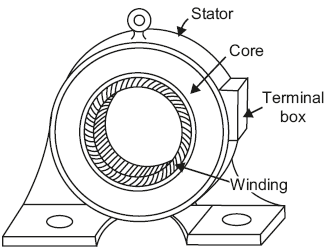 Fig. 12.1 Stator of 3-phase induction motor
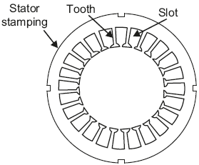 Fig. 12.2 Stator stamping
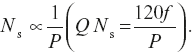
 - Stator winding: The stator core carries a three-phase winding which is usually supplied from a three-phase supply system. The six terminals of the winding (two of each phase) are connected in the terminal box of the machine. The stator of the motor is wound for definite number of poles, the exact number being determined by the requirement of speed. It will be observed that greater the number of poles, the lower is the speed and vice-versa, since
 The three-phase winding may be connected in star or delta externally through a starter.
- Rotor: It is the rotating part of the motor. There are two types of rotors, which are employed in three-phase induction motors, namely squirrel-cage rotor and phase-wound rotor.
- Squirrel-cage rotor: The motors employing this type of rotor are known as ‘squirrel-cage induction motors’. Most of the induction motors are of this type because of simple and rugged construction of rotor. A squirrel-cage rotor consists of a laminated cylindrical core having semi-closed circular slots at the outer periphery. Copper or aluminium bar conductors are placed in these slots and short circuited at each end by copper or aluminium rings, called short-circuiting rings, as shown in Figure 12.3. Thus, the rotor winding is permanently short circuited, and it is not possible to add any external resistance in the rotor circuit.
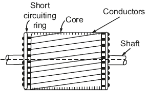 Fig. 12.3 Squirrel cage rotorThe rotor slots are usually not parallel to the shaft but are skewed. Skewing of rotor has the following advantages:
- It reduces humming, thus ensuring quiet running of a motor.
- It results in a smoother torque curves for different positions of the rotor.
- It reduces the magnetic locking of the stator and rotor.
- It increases the rotor resistance due to the increased length of the rotor bar conductors.
- Phase-wound rotor: Phase-wound rotor is also called slip-ring rotor and the motors employing this type of rotor are known as ‘phase-wound or slip-ring induction motors’. Slip-ring rotor consists of a laminated cylindrical core having semi-closed slots at the outer periphery and carries a three-phase insulated winding. The rotor is wound for the same number of poles as that of stator. The three finish terminals are connected together forming star point, and the three start terminals are connected to three copper slip-rings fixed on the shaft (Figure 12.4).
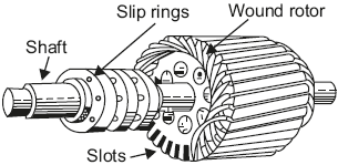 Fig. 12.4 Phase-wound rotorIn this case, depending upon the requirement, any external resistance can be added in the rotor circuit. In this case also, the rotor is skewed.A mild steel shaft is passed through the centre of the rotor and is fixed to it with key. The purpose of shaft is to transfer mechanical power.
- Squirrel-cage rotor: The motors employing this type of rotor are known as ‘squirrel-cage induction motors’. Most of the induction motors are of this type because of simple and rugged construction of rotor. A squirrel-cage rotor consists of a laminated cylindrical core having semi-closed circular slots at the outer periphery. Copper or aluminium bar conductors are placed in these slots and short circuited at each end by copper or aluminium rings, called short-circuiting rings, as shown in Figure 12.3. Thus, the rotor winding is permanently short circuited, and it is not possible to add any external resistance in the rotor circuit.
Leave a Reply