
shows a simplified block diagram of a color television receiver. We will refer to it throughout this chapter. It shows that any receiver must be capable of extracting information from the incoming channels to which it is tuned. The shaded blocks show examples of where demodulation or detection occur for the video and audio signals. Generally the sound uses frequency modulation (FM), while the video signal uses amplitude modulation (AM). The age of digital television and modern data communications uses other techniques. All these methods will be discussed in this chapter.
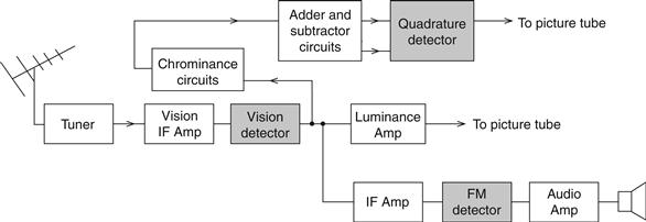
Figure 19.1 Block diagram of color TV receiver
The requirements for modulation are threefold. First, all channels must be separated from one another to avoid interference in the form of intermodulation distortion and crosstalk. Crosstalk occurs when one channel spills over into an adjacent channel, causing interference. Intermodulation distortion occurs when two signals at frequencies f1 and f2 are amplified by a nonlinear device. Second-order products (2f1, f1+f2 and f1–f2) are produced. This might only be troublesome in a broadband system where these products fall within the band. However, third-order components (2f1+f2 and 2f2–f1) usually fall within a system bandwidth, i.e., a particular range of frequencies over which the system operates with good linearity, flat response and minimum distortion, and again cause intermodulation distortion.
In order to achieve good channel separation and avoid interference data, audio and video are generally superimposed on a carrier signal. Each station may have a different carrier or use sophisticated techniques like polarization or frequency sharing, but the point is that frequency translation takes place, with the information signals being shifted to a new frequency.
Second, the physical size of half-wavelength antenna systems would be prohibitive if higher frequencies were not used. In order to understand this, it is convenient to consider the properties of a quarter-wavelength (λ/4) transmission line. Figure 19.2(a) shows an open-ended λ/4 transmission line and its voltage and current distributions. If this is opened out as in Figure 19.2(b), then a λ/2 radiator is produced with the voltage and current distributions as shown. It can be seen that the current is at its maximum at the centre while the voltage is at its minimum. This is equivalent to a low-resistance series resonant circuit which can be tuned to the required transmitted or received channels. However, the point here is that the antenna has an electrical length of half the operating wavelength and is referred to as a λ/2 dipole. (In practice, it is actually 5% shorter than this theoretical value.)
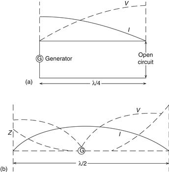
Figure 19.2 (a) Open-ended transmission line and its voltage and current distributions; (b) Transmission line opened out
Consider the case of the speech band being transmitted. This is generally from 300 Hz to 3.4 kHz. The two-dimensional wave equation is used to determine the wavelength:
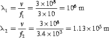
Here v is the velocity of light (3×10⁸m/s). Obviously using a much higher frequency would solve this problem by making the wavelength shorter.
Third, transmitting information in raw form, normally known as the baseband, would be impractical due to the low energy content. Losses between transmission and reception would soon attenuate the signals, with a resultant loss in reception. Modulating the signal by analog or digital methods increases the power to the information and gives a higher signal-to-noise ratio.
In this chapter the following modulation techniques will be discussed together with suitable circuits: amplitude modulation (AM); frequency modulation (FM); frequency shift keying (FSK); phase-shift keying (PSK); and quadrature phase-shift keying (QPSK).
Leave a Reply