
Amplitude Modulation
When the amplitude of a carrier signal is varied in accordance with the information signal, amplitude modulation is produced. This method is mainly used where large power outputs are required for long-distance communications.
Figure 19.3 shows a constant-amplitude, constant-frequency carrier being modulated by a single tone. In practice, many modulating signals may be used. The general expression for the waveform in Figure 19.3(a) is:
![]() (19.1)
(19.1)
where vc is the instantaneous carrier voltage and Vc is the peak amplitude; and ωc is the frequency of the carrier in radians. θ is the phase of the carrier but this will be ignored in the following analysis.
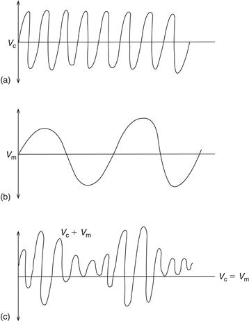
Figure 19.3 (a) Waveform; (b) Modulating signal; (c) Amplitude-modulated wave
The modulating signal in Figure 19.3(b) is given by:
![]() (19.2)
(19.2)
where vm is the instantaneous amplitude of the modulating signal and Vm is the peak amplitude.
The amplitude-modulated wave as shown in Figure 19.3(c) is given by:
![]() (19.3)
(19.3)
![]() (19.4)
(19.4)
Using the trigonometric identity:
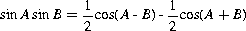
equation (19.4) becomes:
![]() (19.5)
(19.5)
The modulated wave has three frequency components, namely the carrier frequency (fc), the lower sideband (fc–fm) and the upper sideband (fc+fm). These components are represented in the form of a line or spectrum diagram as shown in Figure 19.4. If several modulating tones were present as in the speech band they would be as shown in Figure 19.5.
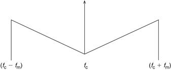
Figure 19.4 Spectrum diagram
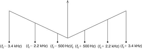
Figure 19.5 With several modulating tones present, as in speech band
Figure 19.3(c) shows two important factors used in practice: the modulating factor and the depth of modulation. The modulating factor (m) is given by:
![]() (19.6)
(19.6)
Expressed as a percentage, this is known as the depth of modulation. Hence, the depth to which the carrier is modulated depends on the amplitude of the carrier and the modulating voltage. The maximum modulation factor used is unity. Exceeding this causes overmodulation and break-up of the signal, and hence some figure less than unity is used in practice.
19.2.2 Power Distribution in an AM Wave
The power which is coupled to an antenna by an AM wave is developed across its resistance. An antenna must be coupled to a transmitter by means of a transmission line or waveguide in order to be excited and hence produce radiation. The antenna input impedance which the feeder ‘sees’ must be known in order to achieve efficient coupling, and this requires a knowledge of transmission line theory.
Note, however, that the antenna input impedance generally has a resistive and reactive part. The reactive element originates from the inherent inductance and capacitance in the antenna. The resistive element of the input impedance originates from the numerous losses in the antenna. The radiated loss (radiation resistance) is the actual power transmitted and is a necessary loss caused by the modulated wave generating power in the antenna. However, other losses are present such as ohmic losses and those due to currents lost in the ground. Because of this it is important that the radiation resistance be much greater than all the other losses. The radiation resistance is generally defined as the equivalent resistance that would dissipate an amount of power equal to the total radiated power when the current through the resistance is equal to the current at the antenna input terminals.
Rearranging equation (19.6) as:

we can rewrite equation (19.5) as:
![]() (19.7)
(19.7)
The r.m.s. power developed across the antenna resistance (Ra) by the carrier and two sidebands is therefore:
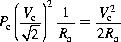
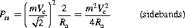
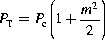
Total power is:
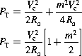 (19.8)
If several pairs of sidebands are involved, equation (19.8) becomes:
![]() (19.9)
(19.9)
Example 19.1
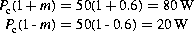
The carrier of an AM transmitter is 50 W and, when modulated by a sinusoidal tone, the power increases to 59 W. Calculate:
(b) the ratio of maximum to minimum values of the wave envelope.
Solution
(a) From equation (19.9):
so,
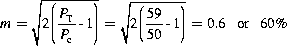
Hence,

Example 19.2
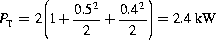
An AM transmitter radiates 2 kW when the carrier is unmodulated and 2.25 kW when the carrier is modulated. When a second modulating signal is applied giving a modulation factor of 0.4, calculate the total radiated power with both signals applied.
Solution
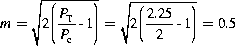
As the carrier power for the unmodulated wave is unchanged,
Example 19.3
An AM signal has a 25 V/100 kHz carrier and is modulated by a 5 kHz tone to a modulation depth of 95%.
(a) Sketch the spectrum diagram of this modulated wave, showing all values.
(b) Determine the bandwidth required.
(c) Calculate the power delivered to a 75 Ω load.
Solution
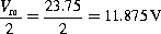
(a) Using our familiar rearrangement of equation (19.6),

The amplitude of the sidebands, from (19.7), is
(See Figure 19.6).
(b) As there is a double sideband, the bandwidth is 10 kHz
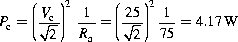
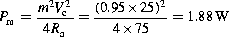
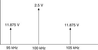
Figure 19.6 Caption not provided.
19.2.3 Amplitude Modulation Techniques
The method of amplitude modulation previously discussed is known as double sideband modulation (DSB). However, this method has a number of disadvantages which can be overcome by filtering out the carrier, one of the sidebands or both. Such a system would have the following advantages:
(a) reduced bandwidth, hence less noise;
(c) increase in efficiency, as power is only transmitted when information is sent;
(d) selective fading is reduced as there is no carrier component to fade below the sideband level and cause sideband beating, which would produce unwanted components;
(e) nonlinearity is reduced as the carrier amplitude is the largest of all the components and this can cause saturation.
Double sideband suppressed carrier (DSBSC) modulation requires the carrier to be reinserted at the receiver with the correct phase and frequency. Single sideband suppressed carrier (SSBSC) modulation only requires the frequency of the reinserted carrier to be correct.
The basic principle of SSBSC is shown in Figure 19.7. The carrier and modulating signal are applied to a balanced modulator (which will be discussed later). The output of the modulator consists of the upper and lower sidebands, but the carrier is suppressed. The band-pass filter then removes one of the sidebands.
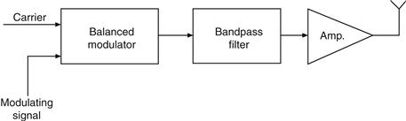
Figure 19.7 Basic principle of single-sideband suppressed carrier modulation
Example 19.4
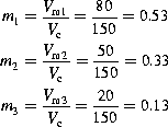
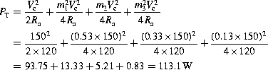
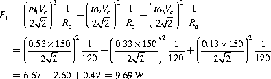
An AM transmitter is modulated by the audio range 20–15 000 Hz. If the carrier frequency is 820 kHz with a voltage level of 150 V, determine:
for the frequency components 400 Hz/80 V, 1 kHz/50 V and 10 kHz/20 V if the antenna load is 120 Ω.
Leave a Reply