
The most frequently used modulator in FM systems is the reactance modulator, which incorporates some method of varying the reactance across the oscillator circuit. This can be done by incorporating a device which changes either its inductive or capacitive reactance, depending on the oscillator involved. With a Colpitts oscillator some type of capacitive modulator would be used; a Hartley oscillator would use an inductive modulator.
The capacitance of a simple signal diode depends on the width of its depletion layer when forward or reverse biased. A particular diode, called a variable reactance diode (varactor for short), is fabricated in such a way that its capacitance is a function of the voltage applied across it.
If a varactor diode is connected across the tuned circuit of an oscillator, and the voltage across the diode is varied, the variation of the diode capacitance will cause a variation in the oscillator’s frequency. The circuit virtually functions as a voltage-to-frequency convertor.
A typical diode FM modulator is shown in Figure 19.15. In this diagram the modulating signal is fed to a transformer which is coupled to a Colpitts oscillator in this case. The varactor diode C4 is reverse biased by Vg, as shown, to a practical point on its characteristics. This reverse bias voltage varies the modulating signal voltage, causing C4 to vary, thus varying the oscillator frequency.
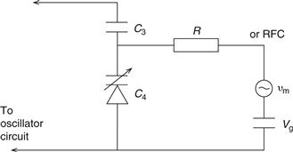
Figure 19.15 Typical diode FM modulator
The radio frequency choke is necessary so that the RF voltage across C4 is not shorted out by the sources vm and Vg. C3 is used to block any DC voltage from the oscillator.
Example 19.11
A reactance modulator is used in an FM transmitter. It consists of a Colpitts oscillator and audio injection circuit as shown in Figure 19.16. The two varactor diodes have a tuneable range from 19.4 to 3 pF. Determine the tuning range of the modulator if the inductance value is L=2 μH.
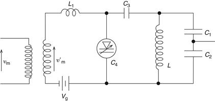
Figure 19.16 Diode FM modulator
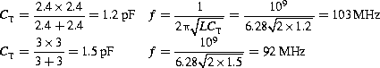
Solution
Leave a Reply