The simplest logic function to implement in CMOS is a NOT gate (Figure 10.20). The small circle, or bobble, on the control input of transistor Tr1 indicates a PMOS transistor. The bobble is used to indicate that this transistor has an active-low control, which means that a logic 0 applied to the control input turns the transistor ON and a logic 1 turns it OFF. The lack of a bobble on the control input of transistor Tr2 indicates an NMOS transistor. The lack of a bobble says that this transistor has an active-high control, which means that a logic 1 applied to the control input turns the transistor ON and a logic 0 turns it OFF.
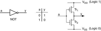
Figure 10.20 CMOS implementation of a NOT gate
Thus, when a logic 0 is applied to input a, transistor Tr1 is turned ON, transistor Tr2 is turned OFF, and output y is connected to logic 1 via Tr1. Similarly, when a logic 1 is applied to input a, transistor Tr1 is turned OFF, transistor Tr2 is turned ON, and output y is connected to logic 0 via Tr2.
Don’t worry if all this seems a bit confusing at first. The main points to remember are that a logic 0 applied to its control input turns the PMOS transistor ON and the NMOS transistor OFF, while a logic 1 turns the PMOS transistor OFF and the NMOS transistor ON. It may help to visualize the NOT gate’s operation in terms of switches rather than transistors (Figure 10.21).
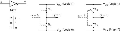
Figure 10.21 NOT gate’s operation represented in terms of switches
Surprisingly, a non-inverting BUF gate is more complex than an inverting NOT gate. This is due to the fact that a BUF gate is constructed from two NOT gates connected in series (one after the other), which means that it requires four transistors (Figure 10.22).
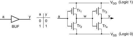
Figure 10.22 CMOS implementation of a BUF gate
The first NOT gate is formed from transistors Tr1 and Tr2, while the second is formed from transistors Tr3 and Tr4. A logic 0 applied to input a is inverted to a logic 1 on w, and then inverted back again to a logic 0 on output y. Similarly, a logic 1 on a is inverted to a logic 0 on w, and then inverted back again to a logic 1 on y.
Around this stage it is not unreasonable to question the need for BUF gates in the first place—after all, their logical function could be achieved using a simple piece of wire. But there’s method to our madness, because BUF gates may actually be used for a number of reasons: for example, to isolate signals, to provide increased drive capability, or to add an element of delay.
Leave a Reply