A similar story occurs in the case of NOR gates and OR gates. First, consider a 2-input NOR, which requires four transistors (Figure 10.26). (A 3-input version could be constructed by adding an additional PMOS transistor in series with Tr1 and Tr2, and an additional NMOS transistor in parallel with Tr3 and Tr4.)
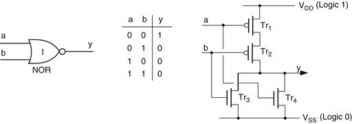
Figure 10.26 CMOS implementation of a 2-input NOR gate
When both a and b are set to logic 0, transistors Tr3 and Tr4 are turned OFF, transistors Tr1 and Tr2 are turned ON, and output y is connected to logic 1 via Tr1 and Tr2. Any other combination of inputs results in one or both of Tr1 and Tr2 being turned OFF, one or both of Tr3 and Tr4 being turned ON, and output y being connected to logic 0 via Tr3 and/or Tr4.
Once again, an OR gate is formed by inverting the output of a NOR with a NOT, which means that a 2-input OR requires six transistors (Figure 10.27).
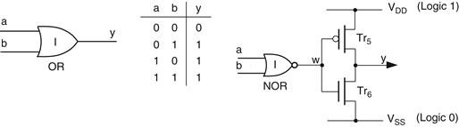
Figure 10.27 CMOS implementation of a 2-input OR ga
Leave a Reply