
Having now defined the parameters that we use to describe operational amplifiers, we shall now consider the desirable characteristics for an “ideal” operational amplifier. These are:
(a) The open-loop voltage gain should be very high (ideally infinite).
(b) The input resistance should be very high (ideally infinite).
(c) The output resistance should be very low (ideally zero).
(d) Full-power bandwidth should be as wide as possible.
(e) Slew rate should be as large as possible.
(f) Input offset should be as small as possible.
The characteristics of most modern integrated circuit operational amplifiers (i.e., “real” operational amplifiers) come very close to those of an “ideal” operational amplifier, as witnessed by the data shown in Table 11.1.
Table 11.1
Comparison of operational amplifier parameters for “ideal” and “real” devices
| Parameter | Ideal | Real |
| Voltage gain | Infinite | 100,000 |
| Input resistance | Infinite | 100 MW |
| Output resistance | Zero | 20 W |
| Bandwidth | Infinite | 2 MHz |
| Slew-rate | Infinite | 10 V/μs |
| Input offset | Zero | Less than 5 mV |
Example 11.3
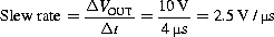
A perfect rectangular pulse is applied to the input of an operational amplifier. If it takes 4 μs for the output voltage to change from -5 V to +5 V, determine the slew rate of the device.
Solution
The slew rate can be determined from:
Example 11.4
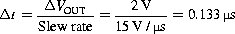
A wideband operational amplifier has a slew rate of 15 V/μs. If the amplifier is used in a circuit with a voltage gain of 20 and a perfect step input of 100 mV is applied to its input, determine the time taken for the output to change level.
Solution
The output voltage change will be 20×100=2,000 mV (or 2 V). Rearranging the formula for slew rate gives:
Leave a Reply