
The most elementary types of filters are constructed from RC networks and are known as passive filters as they dissipate part of the signal power and pass the rest. Figure 17.3(a) shows a passive low-pass filter, while Figure 17.3(b) shows a passive high-pass filter. These form the basis of more sophisticated filters. Each has a cut-off frequency, which may be derived by considering the high-pass filter as a voltage divider. From Figure 17.3(b) we have:
![]() (17.1)
(17.1)
and at the cut-off frequency the gain falls by 3 dB or ![]() . Also at this frequency R=Xc, which gives:
. Also at this frequency R=Xc, which gives:
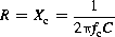
![]() (17.2)
(17.2)
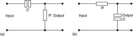
Figure 17.3 (a) Passive low-pass filter; (b) passive high-pass filter
A similar result can be derived for the low pass filter, but for both first-order filters the following points should be considered.
(a) Cascading or connecting these networks in series causes the roll-off of the frequency response to increase by 20 dB/decade for each filter, where “decade” refers to a one-to-ten range of frequencies, such as 1–10 Hz, 10–100 Hz, etc.: observe that on a logarithmic scale, such ranges span an equal distance (see Figures 17.42 and 17.43).
(b) A low-pass filter causes a phase lag between the output and input voltages, while a high-pass filter causes a phase lead between the output and input voltages. This has an important bearing on filters used in certain oscillators.
Leave a Reply