
When you want to connect logic signals from one piece of equipment to another, it is not sufficient to use standard logic devices and make direct gate-to-gate connections, even if they are isolated from the main system. Standard logic is not suited to driving long lines; line terminations are unspecified and noise immunity is low, so that reflections and interference would give unacceptably high data corruption. External logic interfaces must be specially designed for the purpose.
At the same time, it is essential that there is some commonality of interface between different manufacturers’ equipment. This allows the user to connect, say, a computer from manufacturer A to a printer from manufacturer B without worrying about electrical compatibility. There is therefore a need for a standard definition for electrical interface signals.
This need has been recognized for many years, and there are a wide variety of data interchange standards available. The logic of the marketplace has dictated that only a small number of these are dominant. This section will consider the two main commercial ones: EIA-232F and EIA-422. EIA-232F is an update of the popular RS-232C standard published in 1969, to bring it into line with the international CCITT V.24 and V.28 and ISO IS2110 standards. EIA-422 is the same as the earlier RS-422 standard. The prefix changes are cosmetic, purely to identify the source of the standards as the EIA.
13.3.1 EIA-232F
The boom in data communications has led to many products which make interface conformity claims by quoting “RS-232” in their specifications. Some of these claims are in fact quite spurious, and discerning users will regard interface conformity as an indicator of product quality, and test it early on in their evaluation. The major characteristics of the specification are given in Table 13.2. As well as specifying the electrical parameters, EIA-232F also defines the mechanical connections and pin configuration, and the functional description of each data circuit.
Table 13.2
Major electrical characteristics of EIA-232F, EIA-422 and EIA-485
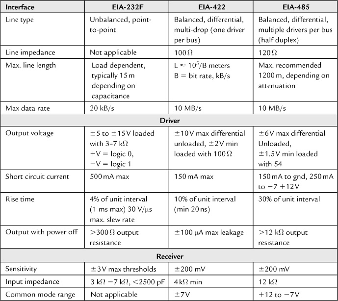
By modern standards the performance of EIA-232F is primitive. It was originally designed to link data terminal equipment (DTE) to modems, known as data communications equipment (DCE). It was also used for data terminal-to-mainframe interfaces. These early applications were relatively low speed, less than 20 kbaud, and used cables shorter than 50 feet. Applications which call for such limited capability are now abundant, hence the standard’s great popularity. Its new revision recognizes this by replacing the phrase “data communication equipment” with “data circuit-terminating equipment,” also abbreviated to DCE. It does not clarify exactly what is a DTE and what is a DCE, and since many applications are simple DTE (computer) to DTE (terminal or printer) connections, it is often open to debate as to what is at which end of the interface. Although a point-to-point connection provides the correct pin terminations for DTE-to-DCE, a useful extra gadget is a cable known as a “null modem” (Figure 13.5) which creates a DTE-to-DTE connection. The common sight of an installation technician crouched over a 9-way connector swapping pins 2 and 3, to make one end’s receiver listen to the other end’s driver, has yet to disappear.
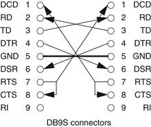
Figure 13.5 The null modem
EIA-232’s transmission distance is limited by its unbalanced design and restricted drive current. The unbalanced design is very susceptible to external noise pick-up and to ground shifts between the driver and receiver. The limited drive current means that the slew rate must be kept slow enough to prevent the cable becoming a transmission line, and this puts a limit on the fastest data rate that can be accommodated. Maximum cable length, originally fixed at 50 feet, is now restricted by a requirement for maximum load capacitance (including receiver input) for each circuit of 2500 pF. As the line length increases so does its capacitance, requiring more current to maintain the same transition time. The graph of Figure 13.6 shows the drive current versus load capacitance required to maintain the 4% transition time relationship at different data rates. In practice, the line length is limited to 3 meters or less for data rates more than 20 kb/s. Most drivers can handle the higher transmission rates over such a short length without drawing excessive supply current.
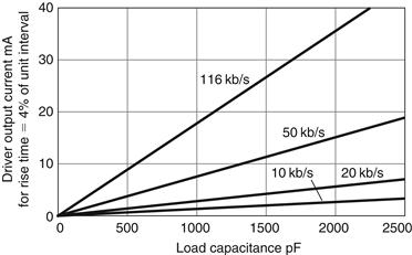
Figure 13.6 EIA-232F transmit driver output current versus CL
Note that there are several common “enhancements” that are not permitted by strict adherence to the standard. EIA-232F makes no provision for tri-stating the driver output, so multiple driver access to one line is not possible. Similarly, paralleling receivers is not allowed unless the combined input impedance is held between 3 kW and 7 kW. It does not consider electrically isolated interfaces: no specification is offered for isolation requirements, despite their desirability. It does not specify the communication data format. The usual “one start bit, eight data bits, two stop bits” format is not part of the standard, just its most common application. It is not directly compatible with another common single-ended standard, EIA-423, although such connections will usually work. Also, you cannot legitimately run EIA-232F off a ±5 V supply rail—the minimum driver output voltage is specified as ±5 V, loaded with 3–7 kW and with an output impedance of 300 W.
The standard calls for slew-rate limiting to 30 V/ms maximum. Although you can do this with an output capacitor, which operates in conjunction with the output transistor’s current limit while it is slewing, this will increase the dissipation, and reduces the maximum possible cable length. It is preferable to use a driver which has on-chip slew rate limiting, requiring no external capacitors and making the slew rate independent of cable length.
13.3.2 EIA-422
Many data communications applications now require data rates in the megabaud region, for which EIA-232F is inadequate. This need is fulfilled by the EIA-422 standard, which is an electrical specification for drivers and receivers for use in a balanced or differential, point-to-point or multi-drop high speed interface using twisted pair cable. Table 13.2 summarizes the EIA-422 specification in comparison with EIA-232F. One driver and up to ten receivers are allowed. The maximum data rate is specified as 10 Mbaud, with a trade-off against cable length; maximum cable length at 100 kbaud is 4000 feet. Note that unlike EIA-232F, EIA-422 does not specify functional or mechanical parameters of the interface. These are included in other standards which incorporate it, notably EIA-449 and EIA-530.
EIA-422 achieves its high-speed and long-distance capabilities by specifying a balanced and terminated design. The balanced design reduces sensitivity to external common mode noise and allows a ground differential of up to a few volts to exist between the driver and one or more of the receivers without affecting the receiver’s thresholds. A cable termination, together with increased driver current, allows fast slew rates which in turn allows high data rates. If the cable is not terminated, serious ringing on the edges occurs which may cause spurious switching in the receiver. The specified termination of 100 W is closely matched to the characteristic impedance of typical twisted pair cables. Only one termination is used, at the receiver at the far end of the cable.
13.3.3 Interface Design
By far the easiest way to realize either EIA-232F or EIA-422 interfaces is to use one of the many specially tailored driver and receiver chip sets that are available. The more common ones, such as the 1488 driver/1489 receiver for EIA-232F or the 26LS31 driver/26LS32 receiver for EIA-422, are available competitively from many sources and in low-power CMOS versions. You can also obtain combined driver/receiver parts so that a small interface can be handled with one IC. Because the 9-pin implementation of EIA-232F is so common, a single package 3-transmitter plus 5-receiver part is also widely sourced. The high-voltage requirement of EIA-232F, typically ±12 V supplies, is addressed by some suppliers who offer on-chip DC-to-DC converters from the +5 V rail.
Figure 13.7 suggests typical interface circuits for the two standards. Note the inclusion of power supply isolating diodes, to protect the rest of the circuit against the inevitable over voltages that will come its way. You can also construct an interface, particularly the simpler EIA-232F, using standard components such as op-amps, comparators, CMOS buffer devices or discrete components if you are prepared to spend some time characterizing the circuit against the requirements of the standard and against expected overload conditions. This may turn out to be marginally cheaper in component cost, but its overall worth is somewhat questionable.
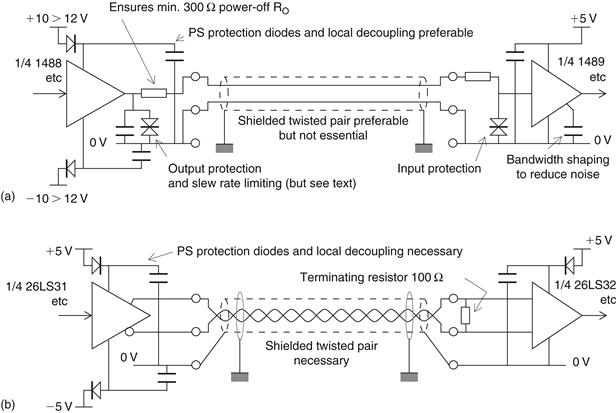
Figure 13.7 Typical EIA-232F and EIA-422 interface circuits (a) EIA-232F; (b) EIA-422
Leave a Reply