
Keith H. Sueker and Tim Williams
Much of the design work in power electronics involves specification of ancillary apparatus in a system. It is essential to a successful design that the engineer knows the general characteristics of these components well enough to permit selection of a suitable device for the intended application. The components in this chapter are usually described in detail in vendor catalog information, but the designer must know the significance of the ratings and how they apply to the job at hand. Competent vendors can be valuable partners in the design process.
Commonly used symbols in power electronics diagrams are shown in Figure 15.1. The utility breaker symbol is generally used in single line drawings of power sources, whereas the industrial symbol is used on schematics. There are no hard and fast rules; however, there are a number of variations on this symbol set.
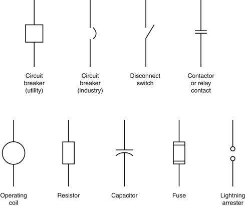
Figure 15.1 Power electronics symbols
Leave a Reply