
The three major dielectric types of capacitors are those with various types of film dielectrics used mostly for power factor correction and R/C snubbers, electrolytic types used for filters, and ceramic types in the smaller ratings. The electrolytics have a much higher energy storage for a given volume, but they are not available in voltages above about 500 V and are generally rated for DC service only. They further have leakage currents and limited ratings for ripple current. Still, their high energy density makes them popular for filters on DC power supplies. Even when operated at rated conditions, electrolytic capacitors have a definite lifetime, because the electrolyte will evaporate over time, especially if the capacitors are operated at high ripple currents or in high ambient temperatures. Design consideration should be given to adequate ventilation or heat sinking.
Film dielectric power factor correction capacitors have replaced most of the earlier types made with paper dielectric. These capacitors are rated by kilovar (kvar) at rated voltage and are available both as single units and three-phase assemblies in one can. Power factor correction capacitors are always fused, either with standard medium-voltage fuses or with expulsion fuses in outdoor installations. The latter discharge a plume of water vapor when ablative material in the fuse tube is evaporated as the fuse clears a fault.
Capacitors applied to a power system can create problems in the presence of harmonics generated by nonlinear loads. The capacitor bank will form a parallel resonance with the source inductance of the utility supply, and if this resonance falls on a harmonic of the line frequency at which harmonic currents are present, the result can be serious overvoltages and/or overcurrents. Good engineering practice is to make a harmonic voltage survey before installing power factor correction capacitors.
Power factor capacitor ratings are described in IEEE 18-2002, IEEE Standard for Shunt Power Capacitors. In summary, they may be operated at maximum conditions of 110% rated rms voltage, 120% of rated peak voltage, 135% of rated kvar, and 180% of rated rms current. Each of these ratings must include any harmonic voltages or currents. When a capacitor is used with a series inductor to form a series resonant harmonic current trap, the increase in voltage at power frequency caused by the inductor must be considered. Most third-harmonic filters and some fifth-harmonic filters may require capacitors rated above the nominal circuit voltage.
Energizing a section of a capacitor bank when the remainder of the bank is on line can result in damaging transient currents. When a single capacitor is connected to a power line, the surge current is limited by the impedance of the source. Within a capacitor bank, however, the only impedance limiting switching current is the small inductance and resistance of the buswork between sections. The charged capacitors will discharge into the incoming capacitor with little current limiting. Each switched section within a capacitor bank should be protected with a current-limiting reactor. Surge currents should be kept within the instantaneous ratings of the capacitors and switchgear.
Some capacitors designed for DC operation are made with a very long sandwich of conductive and dielectric strips rolled into a cylinder. Connections are made at one end of the two conductive strips, a “tab foil” design. Other types are made from a dielectric strip with a foil or deposited film of metal on one side. The film type can evaporate a small area of the metal on an internal failure without damage, and they are advertised as being self-healing. Capacitors designed for R/C snubber circuits, however, are often required to carry high rms currents and must be so rated. These capacitors are also formed from a sandwich of aluminum foil strips and film dielectric rolled into a cylinder, but the foil layers are offset axially so that the connections to the two foil windings can be made all along the two edges of the winding. This arrangement, known as extended foil, lowers the inductance of the capacitor, and the resistive losses are much lower because the current does not have to flow in from one end of the winding. The two constructions are shown in Figure 15.4. In general, DC-rated capacitors should not be used for AC service or R/C snubbers unless they also have an acceptable AC voltage and current rating. Note that snubber capacitors are subjected to repetitive charge and discharge that results in much higher rms currents than would be expected from their capacitance and applied voltage.
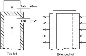
Figure 15.4 Capacitor construction
All capacitors can be connected in series or parallel for higher voltages or capacitances. They may be freely paralleled, but series connections may require the use of a voltage-sharing resistor connected in parallel with each capacitor. Film types operated on AC circuits may not require sharing resistors for series operation, but resistors are required if DC voltage components are present. Without sharing resistors, the DC voltage will distribute in proportion to the highly variable leakage resistances. Sharing resistors must have a resistance low enough to swamp out the leakage resistance variations to a sufficient degree of voltage uniformity. Design guidance is available from vendors.
Yet another version of capacitors is the ceramic type. Made from ceramic material with a high dielectric constant, ceramic capacitors generally have smaller capacitances but are available in high voltage ratings. Such capacitors have a very low self-inductance and may be desirable for some types of snubbers.
Leave a Reply