shows three resistors R1, R2 and R3 connected end to end, i.e., in series, with a battery source of V volts. Since the circuit is closed, a current I will flow and the voltage across each resistor may be determined from the voltmeter readings V1, V2 and V3.
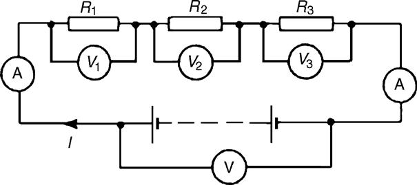
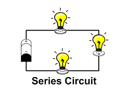
Figure 3.1 : Series circuit
In a series circuit:
(a) the current I is the same in all parts of the circuit; therefore, the same reading is found on each of the two ammeters shown, and,
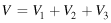
(b) the sum of the voltages V1, V2 and V3 is equal to the total applied voltage, V, i.e.,
From Ohm’s law:
V1 =IR1, V2 =IR2, V3 =IR3 and V =IR
where R is the total circuit resistance.
Since V =V1 +V2 +V3
then IR =IR1 +IR2 +IR3
Dividing throughout by I gives:
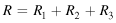
So, for a series circuit, the total resistance is obtained by adding together the values of the separate resistances.
Example 3.1
For the circuit shown in Figure 3.2, determine (a) the battery voltage V, (b) the total resistance of the circuit, and (c) the values of resistance of resistors R1, R2 and R3, given that the voltages across R1, R2 and R3 are 5 V, 2 V and 6 V, respectively.
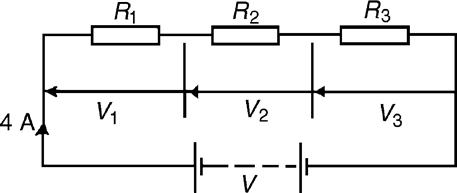
Figure 3.2 : Circuit for Example 3.1
Solution
(a) Battery voltage V=V1+V2+V3
Resistance ![]()
Resistance ![]()
(Check: R1 +R2 +R3 = 1.25 + 0.5 + 1.5 = 3.25 Ω =R)
Example 3.2
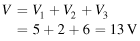
For the circuit shown in Figure 3.3, determine the voltage across resistor R3. If the total resistance of the circuit is 100 Ω, determine the current flowing through resistor R1. Find also the value of resistor R2.
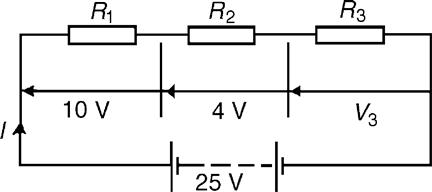
Figure 3.3 : Circuit for Example 3.2
Solution
Voltage across R3, V3 = 25-10-4=11 V
Current ![]() which is the current flowing in each resistor
which is the current flowing in each resistor
Resistance ![]()
Example 3.3
A 12 V battery is connected in a circuit having three series-connected resistors having resistances of 4 Ω, 9 Ω and 11 Ω. Determine the current flowing through, and the voltage across the 9 Ω resistor. Find also the power dissipated in the 11 Ω resistor.
Solution
The circuit diagram is shown in Figure 3.4.
Figure 3.4 : Circuit for Example 3.3
Total resistance R=4+9+11=24 Ω
Current ![]() which is the current in the 9 Ω resistor.
which is the current in the 9 Ω resistor.
Voltage across the 9 Ω resistor, ![]()
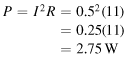
Power dissipated in the 11 Ω resistor,
Leave a Reply