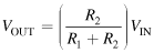
The voltage distribution for the circuit shown in Figure 3.5(a) is given by:
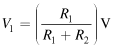
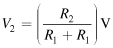
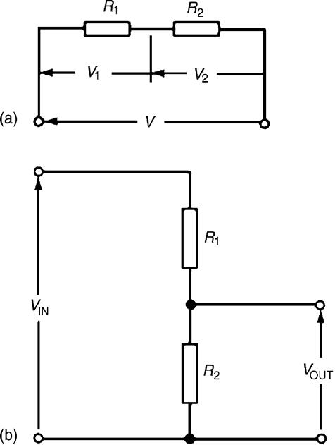
Figure 3.5 : Potential divider circuit
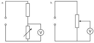
The circuit shown in Figure 3.5(b) is often referred to as a potential divider circuit. Such a circuit can consist of a number of similar elements in series connected across a voltage source, voltages being taken from connections between the elements. Frequently the divider consists of two resistors as shown in Figure 3.5(b), where:
A potential divider is the simplest way of producing a source of lower e.m.f. from a source of higher e.m.f., and is the basic operating mechanism of the potentiometer, a measuring device for accurately measuring potential differences.
Example 3.4
Determine the value of voltage V shown in Figure 3.6.
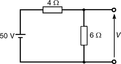
Figure 3.6 : Circuit for Example 3.4
Solution
Figure 3.6 may be redrawn as shown in Figure 3.7, and voltage
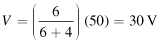
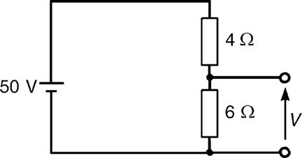
Figure 3.7 : Redrawn version of Figure 3.6
Example 3.5
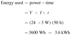
Two resistors are connected in series across a 24 V supply and a current of 3 A flows in the circuit. If one of the resistors has a resistance of 2 Ω determine (a) the value of the other resistor, and (b) the voltage across the 2 Ω resistor. If the circuit is connected for 50 hours, how much energy is used?
Solution
The circuit diagram is shown in Figure 3.8.
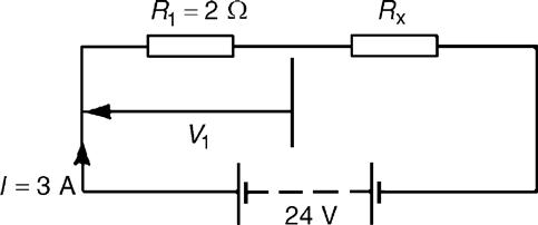
Figure 3.8 : Circuit for Example 3.5
Value of unknown resistance, Rx = 8-2=6Ω
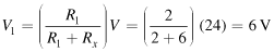
(b) Voltage across 2 Ω resistor, V1 =IR1 = 3×2=6 V
Alternatively, from above,
Leave a Reply