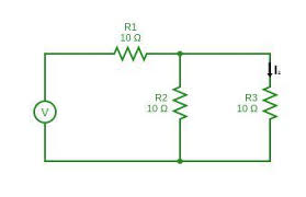
For the circuit shown in Figure 3.18, the total circuit resistance RT is given by:

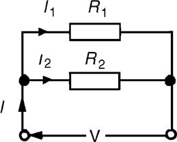
Figure 3.18 : Current division circuit
and ![]()
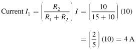
Current ![]()
Similarly,
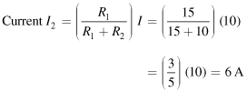
current ![]()
Summarizing, with reference to Figure 3.18:
Example 3.11
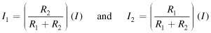
For the series-parallel arrangement shown in Figure 3.19, find (a) the supply current, (b) the current flowing through each resistor and (c) the voltage across each resistor.
Figure 3.19 : Circuit for Example 3.11
Solution
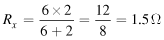
(a) The equivalent resistance Rx of R2 and R3 in parallel is:
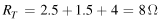
The equivalent resistance RT of R1, Rx and R4 in series is:
Supply current ![]()
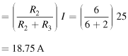
(b) The current flowing through R1 and R4 is 25 A. The current flowing through R2
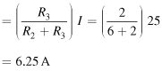
The current flowing through R3
(Note that the currents flowing through R2 and R3 must add up to the total current flowing into the parallel arrangement, i.e., 25 A.)
(c) The equivalent circuit of Figure 3.19 is shown in Figure 3.20.
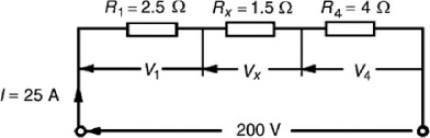
Figure 3.20 : Equivalent circuit of Figure 3.19
voltage across R1, i.e., V1 =IR1 = (25)(2.5) =62.5 V
voltage across Rx, i.e., Vx =IRx = (25)(1.5) =37.5 V
voltage across R4, i.e., V4 =IR4 = (25)(4) =100 V
Hence, the voltage across R2 = voltage across R3 =37.5 V
Example 3.12
For the circuit shown in Figure 3.21 calculate (a) the value of resistor Rx such that the total power dissipated in the circuit is 2.5 kW, and (b) the current flowing in each of the four resistors.
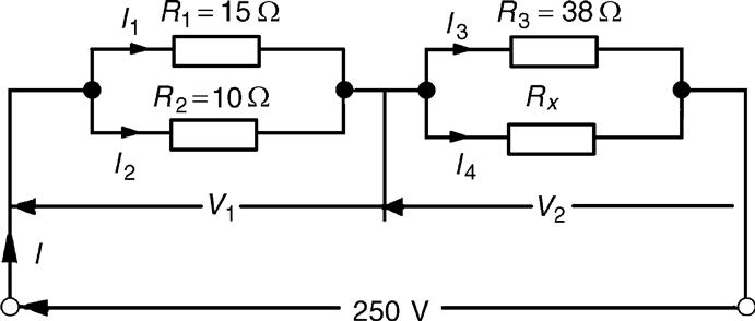
Figure 3.21 : Circuit for Example 3.12
Solution
(a) Power dissipated P =VI watts, hence, 2500 = (250)(I)
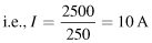
From Ohm’s law, ![]() where RT is the equivalent circuit resistance.
where RT is the equivalent circuit resistance.
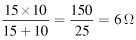
The equivalent resistance of R1 and R2 in parallel is:
The equivalent resistance of resistors R3 and Rx in parallel is equal to 25 Ω – 6 Ω, i.e., 19 Ω.
There are three methods whereby Rx can be determined.
Method 1
The voltage V1 =IR, where R is 6 Ω, from above, i.e., V1 = (10)(6) = 60 V
Hence, V2 = 250 V – 60 V = 190 V = voltage across R3 = voltage across Rx
![]() . Thus, I4 = 5 A also,
. Thus, I4 = 5 A also,
since I = 10 A
Thus, ![]()
Method 2
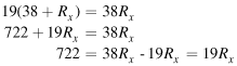
Since the equivalent resistance of R3 and Rx in parallel is 19 Ω,
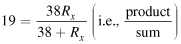
Hence,
Method 3
When two resistors having the same value are connected in parallel, the equivalent resistance is always half the value of one of the resistors. In this case, since RT = 19 Ω and R3 = 38 Ω, then Rx= 38 Ω could have been deduced on sight.
From part (a), method 1, I3 =I4 =5 A
Example 3.13
For the arrangement shown in Figure 3.22, find the current Ix.
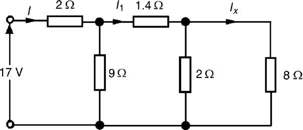
Figure 3.22 : Circuit for Example 3.13
Solution
Commencing at the right-hand side of the arrangement shown in Figure 3.24, the circuit is gradually reduced in stages as shown in Figures 3.23(a)–(d).
From Figure 3.23(d), ![]()
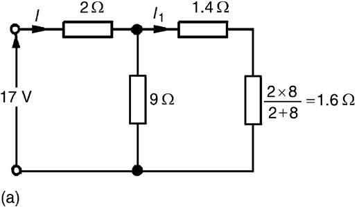
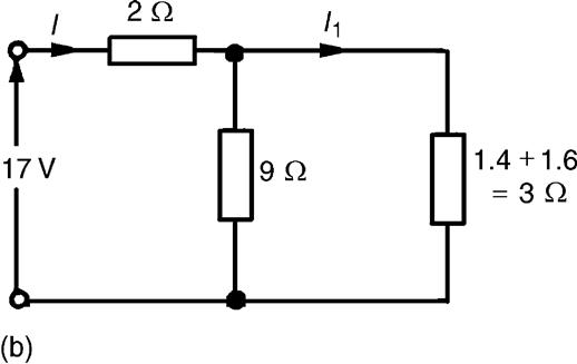
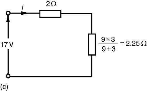
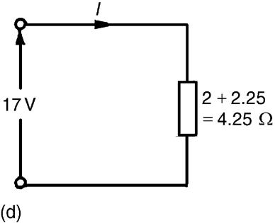
Figure 3.23 : Solution to Example 3.13, in four stages
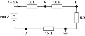
Figure 3.24 : Relative voltage
From Figure 3.23(b), ![]()
From Figure 3.22, ![]()
3.5 Relative and Absolute Voltages
In an electrical circuit, the voltage at any point can be quoted as being “with reference to” (w.r.t.) any other point in the circuit. Consider the circuit shown in Figure 3.24. The total resistance,
If a voltage at point A is quoted with reference to point B then the voltage is written as VAB. This is known as a relative voltage. In the circuit shown in Figure 3.24, the voltage at A w.r.t. B is I × 50, i.e., 2×50=100 V and is written as VAB = 100 V.
It must also be indicated whether the voltage at A w.r.t. B is closer to the positive terminal or the negative terminal of the supply source. Point A is nearer to the positive terminal than B so is written as VAB = 100 V or VAB = +100 V or VAB = 100 V +ve.
If no positive or negative is included, then the voltage is always taken to be positive.
If the voltage at B w.r.t. A is required, then VBA is negative and is written as

If the reference point is changed to the earth point then any voltage taken w.r.t. the earth is known as an absolute potential. If the absolute voltage of A in Figure 3.24 is required, then this will be the sum of the voltages across the 50 Ω and 5 Ω resistors, i.e., 100+10=110 V and is written as VA = 110 V or VA = +110 V or VA = 110 V +ve, positive since moving from the earth point to point A is moving towards the positive terminal of the source. If the voltage is negative w.r.t. earth then this must be indicated; for example, VC = 30 V negative w.r.t. earth, and is written as VC = -30 V or VC = 30 V -ve.
Example 3.14
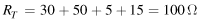
For the circuit shown in Figure 3.25, calculate (a) the voltage drop across the 4 kΩ resistor, (b) the current through the 5 kΩ resistor, (c) the power developed in the 1.5 kΩ resistor, (d) the voltage at point X w.r.t. earth, and (e) the absolute voltage at point X.
Figure 3.25 : Circuit for Example 3.14
Solution
(a) Total circuit resistance, RT = [(1+4) kΩ in parallel with 5 kΩ] in series with 1.5 kΩ
Total circuit current, ![]()
By current division, current in top branch
Hence, volt drop across 4 kΩresistor
(b) Current through the 5 kΩresistor
(c) Power in the 1.5 kΩresistor

(d) The voltage at the earth point is 0 volts. The volt drop across the 4 kΩ is 12 V, from part (a). Since moving from the earth point to point X is moving towards the negative terminal of the voltage source, the voltage at point X w.r.t. earth is –12 V.
(e) The absolute voltage at point X means the voltage at point X w.r.t. earth; therefore, the absolute voltage at point X is -12 V. Questions (d) and (e) mean the same thing.
Leave a Reply