
Simple AC circuits may be analyzed by using phasor diagrams. However, when circuits become more complicated, analysis is considerably simplified by using complex numbers. It is essential that the basic operations used with complex numbers, as outlined in this chapter thus far, are thoroughly understood before proceeding with AC circuit analysis.
7.5.1 Series AC Circuits
7.5.1.1 Pure Resistance
In an AC circuit containing resistance R only (see Figure 7.4(a)), the current IR is in phase with the applied voltage VR as shown in the phasor diagram of Figure 7.4(b). The phasor diagram may be superimposed on the Argand diagram as shown in Figure 7.4(c). The impedance Z of the circuit is given by:
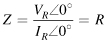
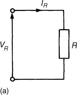
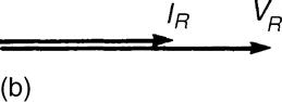
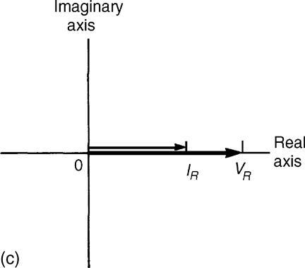
Figure 7.4 (a) Circuit diagram; (b) Phasor diagram; (c) Argand diagram
7.5.1.2 Pure Inductance
In an AC circuit containing pure inductance L only (see Figure 7.5(a)), the current IL lags the applied voltage VL by 90° as shown in the phasor diagram of Figure 7.5(b). The phasor diagram may be superimposed on the Argand diagram as shown in Figure 7.5(c). The impedance Z of the circuit is given by:
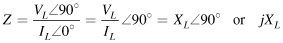
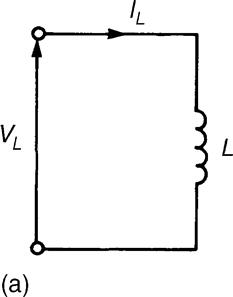
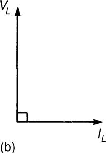
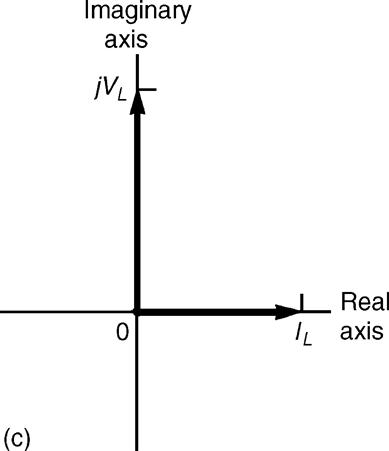
Figure 7.5 (a) Circuit diagram; (b) Phasor diagram; (c) Argand diagram
where XL is the inductive reactance given by:
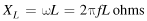
where f is the frequency in hertz and L is the inductance in henrys.
7.5.1.3 Pure Capacitance
In an AC circuit containing pure capacitance only (see Figure 7.5(a)), the current IC leads the applied voltage VC by 90° as shown in the phasor diagram of Figure 7.5(b). The phasor diagram may be superimposed on the Argand diagram as shown in Figure 7.5(c). The impedance Z of the circuit is given by:

where XC is the capacitive reactance given by:
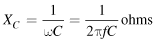
where C is the capacitance in farads. FIGURE 7.6
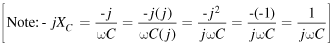
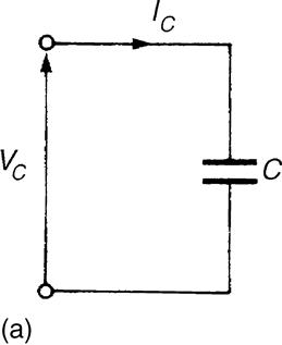
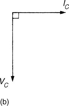
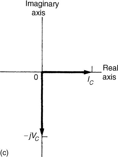
Figure 7.6 (a) Circuit diagram; (b) Phasor diagram; (c) Argand diagram
7.5.1.4 R–L Series Circuit
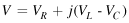
In an AC circuit containing resistance R and inductance L in series (see Figure 7.7(a)), the applied voltage V is the phasor sum of VR and VL as shown in the phasor diagram of Figure 7.7(b). The current I lags the applied voltage V by an angle lying between 0° and 90°—the actual value depending on the values of VR and VL, which depend on the values of R and L. The circuit phase angle, that is, the angle between the current and the applied voltage, is shown as angle ϕ in the phasor diagram. In any series circuit the current is common to all components and is taken as the reference phasor in Figure 7.7(b). The phasor diagram may be superimposed on the Argand diagram as shown in Figure 7.7(c), where it may be seen that in complex form the supply voltage V is given by:

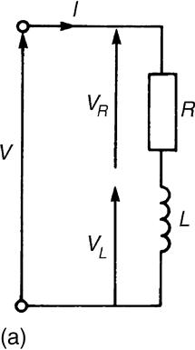
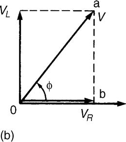
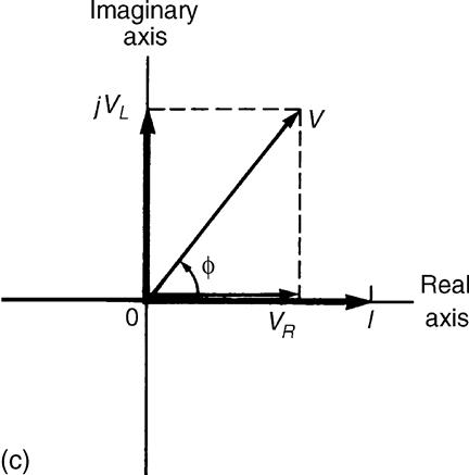
Figure 7.7 (a) Circuit diagram; (b) Phasor diagram; (c) Argand diagram
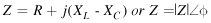
Figure 7.8(a) shows the voltage triangle that is derived from the phasor diagram of Figure 7.8(b) (triangle Oab). If each side of the voltage triangle is divided by current I, then the impedance triangle of Figure 7.8(b) is derived. The impedance triangle may be superimposed on the Argand diagram, as shown in Figure 7.8(c), where it may be seen that in complex form the impedance Z is given by:

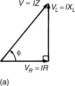
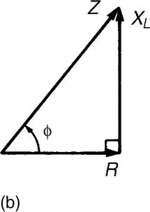
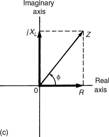
Figure 7.8 (a) Voltage triangle; (b) Impedance triangle; (c) Argand diagram
For example, an impedance expressed as (3+j4) Ω means that the resistance is 3 Ω and the inductive reactance is 4 Ω.
In polar form, Z=|Z| ∠ϕ where, from the impedance triangle, the modulus of impedance ![]() and the circuit phase angle ϕ=tan-1 (XL/R) lagging.
and the circuit phase angle ϕ=tan-1 (XL/R) lagging.
7.5.1.5 R-C Series Circuit
In an AC circuit containing resistance R and capacitance C in series (see Figure 7.9(a)), the applied voltage V is the phasor sum of VR and VC as shown in the phasor diagram of Figure 7.9(b). The current I leads the applied voltage V by an angle lying between 0°and 90°—the actual value depending on the values of VR and VC, which depend on the values of R and C. The circuit phase angle is shown as angle ϕ in the phasor diagram. The phasor diagram may be superimposed on the Argand diagram as shown in Figure 7.9(c), where it may be seen that in complex form the supply voltage V is given by:

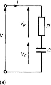
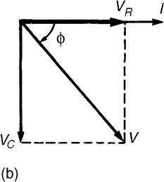
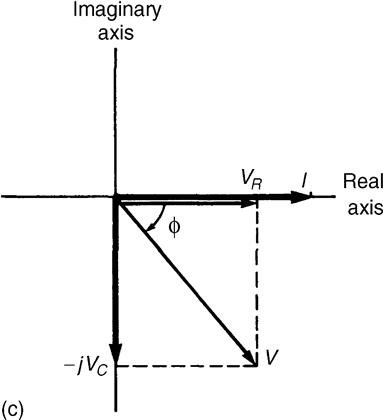
Figure 7.9 (a) Circuit diagram; (b) Phasor diagram; (c) Argand diagram
Figure 7.10(a) shows the voltage triangle that is derived from the phasor diagram of Figure 7.10(b). If each side of the voltage triangle is divided by current I, the impedance triangle is derived as shown in Figure 7.10(b). The impedance triangle may be superimposed on the Argand diagram as shown in Figure 7.10(c), where it may be seen that in complex form the impedance Z is given by:

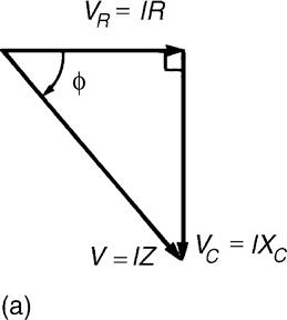
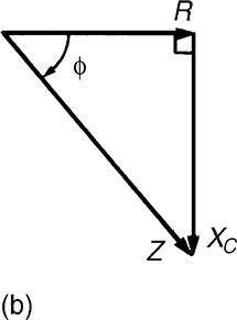
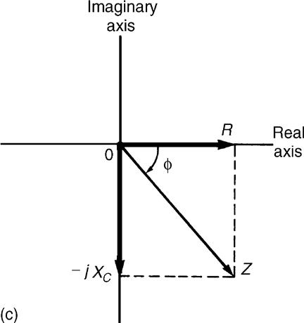
Figure 7.10 (a) Voltage triangle; (b) Impedance triangle; (c) Argand diagram
Thus, for example, an impedance expressed as (9 –j14) Ω means that the resistance is 9 Ω and the capacitive reactance XC is 14 Ω.
In polar form, Z=|Z| ∠ϕ where, from the impedance triangle, angle, ![]() and ϕ=tan-1 (XC/R) leading.
and ϕ=tan-1 (XC/R) leading.
7.5.1.6 R-L-C Series Circuit
In an AC circuit containing resistance R, inductance L and capacitance C in series (see Figure 7.10(a)), the applied voltage V is the phasor sum of VR, VL and VC as shown in the phasor diagram of Figure 7.10(b) (where the condition VL >VC is shown). The phasor diagram may be superimposed on the Argand diagram as shown in Figure 7.10(c), where it may be seen that in complex form the supply voltage V is given by:
From the voltage triangle the impedance triangle is derived and superimposing this on the Argand diagram gives, in complex form,
Impedance
where,

When VL=VC, XL=XC and the applied voltage V and the current I are in phase. This effect is called series resonance. FIGURE 7.11
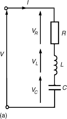
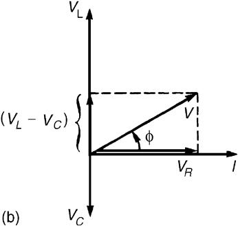
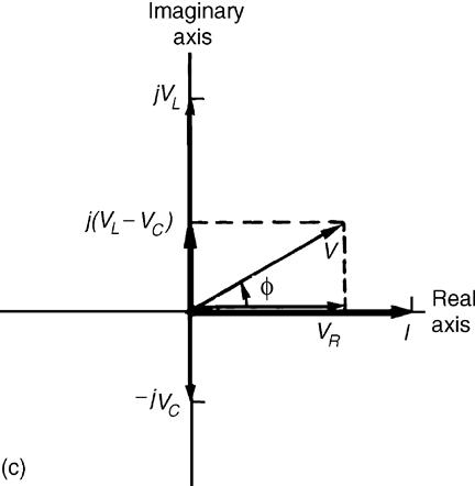
Figure 7.11 (a) Circuit diagram; (b) Phasor diagram; (c) Argand diagram
7.5.1.7 General Series Circuit
In an AC circuit containing several impedances connected in series, say, Z1, Z2, Z3, … , Zn, then the total equivalent impedance ZT is given by:

Example 7.5
Determine the values of the resistance and the series-connected inductance or capacitance for each of the following impedances: (a) (12+j5) Ω; (b) –j40 Ω; (c) 30∠60°Ω; (d) 2.20×10⁶∠–30°Ω. Assume for each a frequency of 50 Hz.
Solution
.
(a) From Section 24.2(d), for an R–L series circuit, impedance Z=R+jXL.
Thus, Z=(12+j5) Ω represents a resistance of 12 Ω and an inductive reactance of 5 Ω in series.
Since inductive reactance XL=2πfL,
Inductance ![]()
So, the inductance is 15.9 mH.
Thus, an impedance (12+j5) Ω represents a resistance of 12 Ω in series with an inductance of 15.9 mH
(b) For a purely capacitive circuit, impedance Z=–jXC.
Thus, Z=–j40 Ω represents zero resistance and a capacitive reactance of 40 Ω.
Since capacitive reactance XC=1/(2πfC),
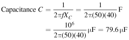
Thus, an impedance –j40 Ω represents a pure capacitor of capacitance 79.6 μF.
(c) 30∠60°=30(cos 60°+j sin 60°)=15+j25.98
Thus, Z=30∠60°Ω=(15+j25.98) Ω represents a resistance of 15 Ω and an inductive reactance of 25.98 Ω in series.
Since XL=2πfL,
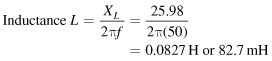
Thus, an impedance 30∠60°Ω represents a resistance of 15 Ω in series with an inductance of 82.7 mH.
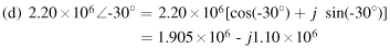

represents a resistance of 1.905×10⁶ Ω (i.e., 1.905 MΩ) and a capacitive reactance of 1.10×10⁶ Ω in series.
Since capacitive reactance XC=1/(2πfC),
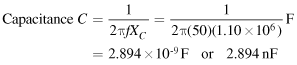
Thus, an impedance 2.2×10⁶∠–30°Ωrepresents a resistance of 1.905 MΩ in series with a 2.894 nF capacitor.
Example 7.6
Determine, in polar and rectangular forms, the current flowing in an inductor of negligible resistance and inductance 159.2 mH when it is connected to a 250 V, 50 Hz supply.
Solution
Inductive reactance

Thus, circuit impedance Z=(0+j50) Ω=50∠90°Ω
Supply voltage, ![]()
(Note that since the voltage is given as 250 V, this is assumed to mean 250∠0°V or (250+j0)V.)
Hence, current 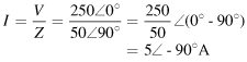
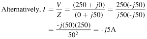
which is the same as 5∠–90°A
Example 7.7
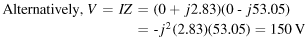
A 3-μF capacitor is connected to a supply of frequency 1 kHz and a current of 2.83∠90 A flows. Determine the value of the supply voltage.
Solution
Hence, circuit impedance

Current ![]()
Supply voltage, ![]()
Example 7.8
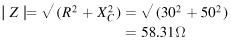
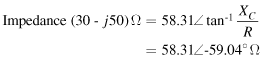
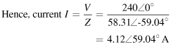
The impedance of an electrical circuit is (30 –j50) ohms. Determine (a) the resistance, (b) the capacitance, (c) the modulus of the impedance, and (d) the current flowing and its phase angle, when the circuit is connected to a 240 V, 50 Hz supply.
Solution
.
(a) Since impedance Z=(30 –j50) Ω, the resistance is 30 ohms and the capacitive reactance is 50 Ω.
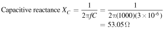
(b) Since XC=1/(2πfC), capacitance,

Example 7.9
A 200 V, 50 Hz supply is connected across a coil of negligible resistance and inductance 0.15 H connected in series with a 32 Ω resistor. Determine (a) the impedance of the circuit, (b) the current and circuit phase angle, (c) the voltage across the 32 Ω resistor, and (d) the voltage across the coil.
Solution
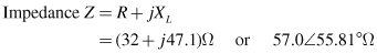
The circuit diagram is shown in Figure 7.12.
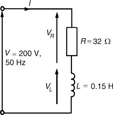
Figure 7.12 Circuit diagram for Example 7.9
(b) Current ![]()
i.e., the current is 3.51A lagging the voltage by 55.81°
(c) Voltage across the 32 Ω resistor,


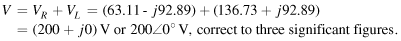
The phasor sum of VR and VL is the supply voltage V as shown in the phasor diagram of Figure 7.13.
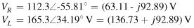
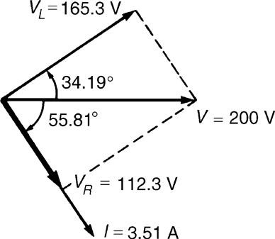
Figure 7.13 Phasor diagram for Example 7.9
Hence,
Example 7.10
Determine the value of impedance if a current of (7+j16)A flows in a circuit when the supply voltage is (120+j200)V. If the frequency of the supply is 5 MHz, determine the value of the components forming the series circuit.
Solution
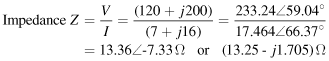
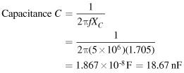
The series circuit consists of a 13.25 Ωresistor and a capacitor of capacitive reactance 1.705 Ω.
Since ![]()
Leave a Reply