We now wish to push the circuit analogy further and explore the possibility
of universal quantum gates. Let’s start with single-qubit gates. We’ve seen
that these are 2 ×2 unitary matrices, which take a point on the Bloch sphere
to another. It is easy to see that there are infinitely many possible 1-qubit
gates. These however cannot form a universal set since controlled operations
cannot be implemented by taking direct products of 1-qubit gates. How do we
implement controlled gates in general?
7.4.1 Controlled-U gate
Working toward a general construction for a controlled U gate for arbitrary
U makes use of the following representation for U :
Theorem 7.1. Any unitary 2 × 2 matrix can be decomposed as
U = e
iθ
A σ
x
B σ
x
C, s.t A B C = , (7.26)
where A, B, and C are also unitary.
Proof. The proof hinges on the fact that any unitary matrix implements a
rotation on the Bloch sphere, up to an over-all phase factor e
iθ
. Suppose V
is some unitary matrix. The matrix V σ
x
V
†
is also unitary, so that it can be
represented (see Equation 7.11) as
V σ
x
V
†
= a
0
+ ~a · ~σ, a
2
0
+ ~a ·~a = 1.
But V σ
x
V
†
is a similarity transformation of σ
x
. So it must preserve its trace,
which is zero. Therefore a
0
= 0 and
V σ
x
V
†
= ˆa · ~σ for a real unit ˆa.
Note that σ
x
= ˆx · ~σ. Then V σ
x
V
†
must be rotating ˆx to a new direction ˆa.
Similarly, another unitary W will achieve
W σ
x
W
†
=
ˆ
b · ~σ for a real unit
ˆ
b.
Thus we have
V σ
x
V
†
W σ
x
W
†
= (ˆa · ~σ) (
ˆ
b · ~σ)
= ˆa ·
ˆ
b + i ˆa ×
ˆ
b · ~σ.
(Refer to Equation 3.34 you proved in one of the problems of Chapter 3.) We
can now think of ˆa and
ˆ
b as directions with an angle γ between them so that
ˆa ·
ˆ
b = cos γ, ˆa ×
ˆ
b = sin γ ˆn, which is perpendicular to ˆa and
ˆ
b
Processing
Then we can construct
U = e
iθ
V σ
x
V
†
W σ
x
W
†
= e
iθ
(cos γ + i sin γ ˆn · ~σ)
= e
iθ
e
iγ ˆn·~σ
,
which is a valid representation for a unitary operator! If we identify
V = A, V
†
W = B and W
†
= C,
then we have the requisite representation for U.
We can implement C-V σ
x
V
†
W σ
x
W
†
by the circuit of Figure (7.16).
|xi
• •
|yi
W
†
W
V
†
V
FIGURE 7.16: Circuit to evaluate C-U up to the phase factor
It is straightforward to see that when x = 0, the output is V V
†
W W
†
y = y,
and when x = 1, the output is V σ
x
V
†
W σ
x
W
†
y = Uy up to the phase. So
this gives C-U up to the phase factor. We need to additionally implement the
controlled phase C-Θ where
Θ =
“
e
iθ
0
0 e
iθ
.
#
Now check that
C−Θ =
“
0
0 Θ
#
=
“
1 0
0 e
iθ
#
⊗ .
We then have the implementation of the full C-U illustrated in Fig-
ure (7.17), that uses only CNOT gates and single-qubit gates.
|xi
• •
“
1 0
0 e
iθ
#
|yi
W
V W
†
W
FIGURE 7.17: Implementation of controlled U gate.
Here, V and W are arbitrary unitaries. We are now half-way through in our
quest for universal quantum gates, of which one set is given in the following
theorem:
Quantum Gates and Circuits 137
Theorem 7.2. Universal Quantum Gates: the CNOT gate along with
single-qubit gates is universal.
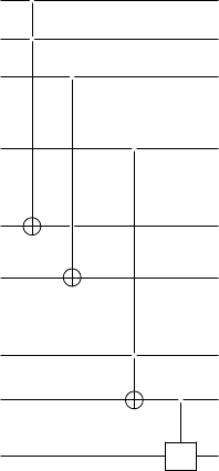
How do we prove this? Now classically, the Toffoli gate, which is a C-
C-NOT gate, is universal. We’ll now show that given our construction for
C-U gates, we can build doubly controlled C-C-U gates as follows. Consider
a unitary Q such that Q
2
= U . Then we can build a C-C-U by the circuit
in Figure 7.18. Let’s work through this circuit algebraically to show that it
|xi
• • •
|yi
• •
|zi
Q
Q
†
Q
FIGURE 7.18: Implementation of C-C-U gate.
works as expected:
|xi|yi|zi → |xi|yi Q
x
|zi
→ |xi|x ⊕ yi Q
x
|zi
→ |xi|x ⊕ yi (Q
†
)
x⊕y
Q
x
|zi
→ |xi|yi (Q
−1
)
x⊕y
Q
x
|zi
→ |xi|yi Q
y
Q
−x⊕y
Q
x
|zi
The power of Q that acts on |zi in the end is
y − (x ⊕ y) + x = y −(x + y − 2xy) + x = 2xy.
So the effect of this circuit is
|zi → Q
2xy
|zi = U
xy
|zi,
which is exactly what we want. We can for instance construct a quantum
Toffoli gate by using Q
2
= X. One such “square root of NOT” gate is
√
X =
1
2
“
1 + i 1 − i
1 − i 1 + i
#
. (7.27)
Example 7.4.1. A useful question to ask in designing circuits is how to min-
imize the number of basic gates required for a given implementation. In our
construction for the C-C-U gate given above, we require 2 CNOTs plus 2
CNOTs for each C-Q gate, that is a total of 8 CNOTs. Can we be more
frugal? Here is an example from Mermin [48] of a construction for a Toffoli
138 Introduction to Quantum Physics and Information Processing
gate using only 4 CNOT gates. Consider two unitaries A and B such that
A
2
= = B
2
. This means that
A = V
†
XV, B = W
†
XW.
Thus each C-A and C-B gate requires only one CNOT gate and two single-
qubit gates.
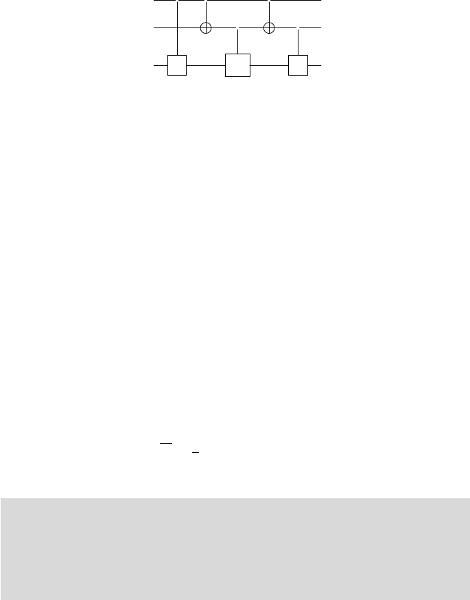
You should be able to work out that the circuit of Figure 7.19 implements
a doubly controlled (BA)
2
gate, up to a phase α.
• •
“
1 0
0 e
iα
#
• •
B A B A
FIGURE 7.19: Efficient implementation of a Toffoli gate.
Now
AB = V
†
XV W
†
XW = (ˆa · ~σ)(
ˆ
b · ~σ)
= ˆa ·
ˆ
b + i(ˆa ×
ˆ
b) · ~σ.
If we choose the angle between ˆa and
ˆ
b to be π/4, and also let ˆa ×
ˆ
b point
along ˆx, then we have
AB = cos
π
4
+ i sin
π
4
σ
x
=
1
√
2
( + iX)
(AB)
2
=
1
2
( + 2iX + (−X)
2
) = iX.
Thus we can regard AB as the square-root of X up to a phase of i. This phase
can be cancelled if we choose α = −π/2 and this circuit implements a Toffoli
gate with just 4 CNOTs and single-qubit gates.
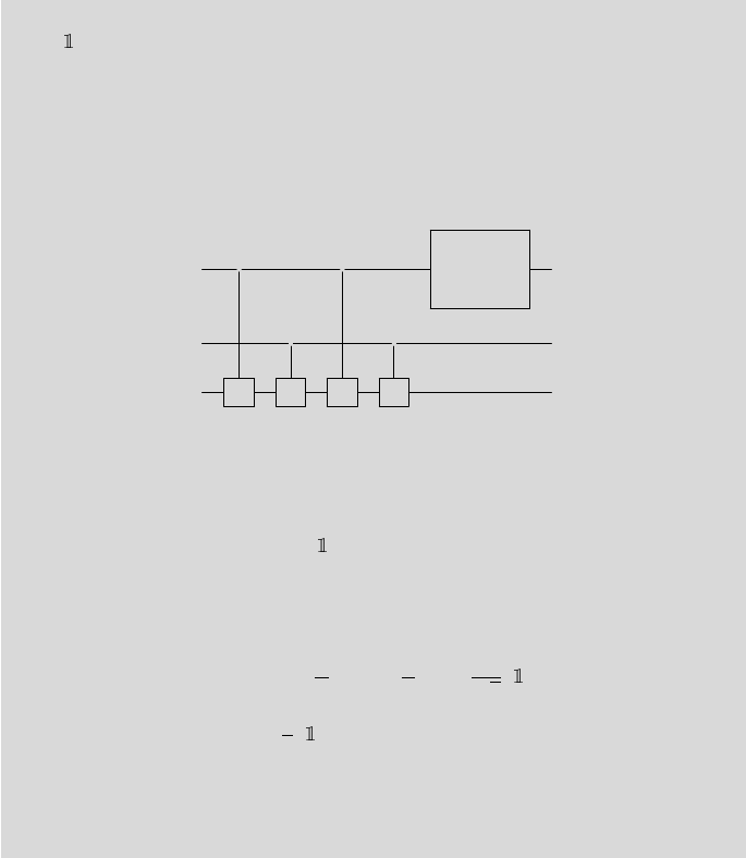
One can construct multiply controlled U gates, a C
n
-U gate, by a cascad-
ing circuit using n control bits, Toffoli gates and n − 1 auxiliary bits, as in
Figure 7.20.
Verify that this works! The use of the Toffoli gates performs an “AND” of
all the control bits, which finally controls the U gate. Also note that all the
auxiliaries can be returned to their original state of |0i by adding the reverse
of each of the actions after obtaining C
n
-U.
Quantum Gates and Circuits 139
x
n−1
•
x
n−2
•
x
n−3
•
n controls
.
.
.
.
.
.
.
.
.
.
.
.
.
.
.
x
0
•
0
•
0
n − 1
.
.
.
.
.
.
.
.
.
.
.
.
.
.
.
.
.
.
auxiliaries
0
•
0
•
y
U
U
x
0
x
1
…x
n−1
y
FIGURE 7.20: Implementation of C
n
-U gate
Leave a Reply