
Classically, the repetition code is the simplest way of introducing redun-
dancy to protect information. Assume that noise in the channel is modelled
as a bit flip with probability p (and hence 1 − p for not flipping). This is
schematised in Figure 10.2. This is known as the binary symmetric channel.
0
1−p
//
p
”
0
1
1−p
//
p
77
1
FIGURE 10.2: Binary symmetric channel for bit flips.
To protect against errors, each logical bit, indicated by the tilde, is encoded
using three identical physical bits.
0 →
˜
0 = 000, 1 →
˜
1 = 111. (10.1)
If p is sufficiently small, then the majority value decides what the original bit
was. The total probability of error is the sum of probability that 2 bits flipped
and that 3 bits flipped which is 3p
(
1 −p) + p
3
= 3p
2
−2p
3
. If p < 1/2, this is
much smaller than the probability of error without encoding, which is p.
Now suppose we have a quantum channel that was susceptible to only
qubit flips. We can model such a channel by X acting with probability p on
a state passing through the channel. The quantum equivalent of the 3-bit
repetition code represents each basis state by 3 identical qubits in the same
basis state:
|0i → |
˜
0i = |000i; |1i → |
˜
1i = |111i (10.2)
Quantum Error Correction 199
so that an arbitrary state is encoded as
|ψi = α|0i + β|1i −→ |
˜
ψi = α|000i + β|111i. (10.3)
This encoding process is easily achieved by the circuit of Figure 10.3.
|ψi
• •
|0i
|
˜
ψi
|0i
FIGURE 10.3: Encoding circuit for the 3-qubit bit-flip code.
This does not make three copies of the original state, however, and neither
can we try to measure the state after it passes through the noise to check how
it has changed, as that would destroy the superposition. If we assume that
the channel is capable of flipping only one qubit, then the codeword state |
˜
ψi
could have changed into four possible output states:
S
0
: |
˜
ψi → |ψ
0
i = |
˜
ψi = α|000i + β|111i (10.4a)
S
1
: |
˜
ψi → |ψ
1
i = X
1
|
˜
ψi = α|001i + β|110i (10.4b)
S
2
: |
˜
ψi → |ψ
2
i = X
2
|
˜
ψi = α|010i + β|101i (10.4c)
S
3
: |
˜
ψi → |ψ
3
i = X
3
|
˜
ψi = α|100i + β|011i (10.4d)
These states are known as syndromes, since we can diagnose the affliction due
to noise by detecting which one occurred! But how do we detect the syndrome
without measuring or copying? The way out is to use ancillary qubits, with
controlled gates acting on them and to measure the ancillaries. We have to
ensure that we do not get any information about the original state by this
measurement, but still detect the syndrome. Note that the four syndrome
states are all mutually orthogonal. Therefore it is possible to distinguish them
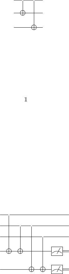
by measuring a 2-qubit ancilla. Consider the circuit in Figure 10.4. Each qubit
of the input state is indicated by its label.
3
•
|
¯
ψi
2
• •
1
•
|0i
x
|0i
y
FIGURE 10.4: Syndrome measurement for the 3-qubit bit-flip code
200 Introduction to Quantum Physics and Information Processing
TABLE 10.1: Syndrome measurement: outcomes.
Syndrome xy
|ψ
0
i 00
|ψ
1
i 01
|ψ
2
i 11
|ψ
3
i 10
You can verify that the measured 2-bit number xy give you the syndrome
as in Table 10.1.
The information contained in the input state |
˜
ψi is not revealed by the
measurements. It is easy to see that for each syndrome |ψ
i
i, the error can be
corrected by applying X on the i
th
qubit. This action can be linked to the xy
values, which control the action of X on the corresponding qubit: X
x¯y
on the
first qubit, X
xy
on the second, and X
¯xy
on the last qubit of the codeword.
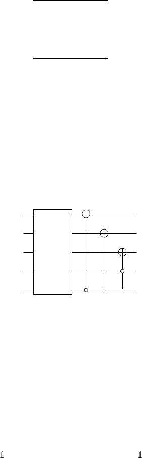
The nice thing about expressing it as this controlled action is that the
process can be automated, bypassing the need for measurement, by applying
suitable controlled gates as in Figure 10.5.
3
SM
|
¯
ψi
2
1
|0i
• •
|0i
• •
FIGURE 10.5: Error detection and correction for 3-qubit bit-flip code. Here
SM is the syndrome measurement circuit
Leave a Reply