
All foundations settle to some extent as the earth materials around and beneath them adjust to the loads of the building. Foundations on bedrock settle a negligible amount. Foundations in other types of soil may settle much more. As an extreme example, Mexico City’s Palace of Fine Arts has settled more than 15 feet (4.5 m) into the clay soil on which it is founded since it was constructed in the early 1930s. However, building foundation settlement is normally limited to amounts measured in millimeters or fractions of an inch.
We must never trust too hastily to any ground. . . . I have seen a tower at Mestre, a place belonging to the Venetians, which, in a few years after it was built, made its way through the ground it stood upon . . . and buried itself in earth up to the very battlements.
Leon Battista Alberti, Ten Books on Architecture, 1452.
Where foundation settlement occurs at roughly the same rate throughout all portions of a building, it is termed uniform settlement. Settlement that occurs at differing rates between different portions of a building is termed differential settlement. When all parts of a building rest on the same kind of soil, and the loads on the building and the design of its structural system are uniform throughout, differential settlement is normally not a concern. However, where soils, loads, or structural systems differ between parts of a building, different parts of the building structure may settle by substantially different amounts, the frame of the building may become distorted, floors may slope, walls and glass may crack, and doors and windows may not work properly (Figure 2.1). Most foundation failures are attributable to excessive differential settlement. Gross failure of a foundation, in which the soil fails completely to support the building, is extremely rare.
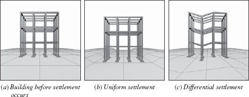
FIGURE 2.1 Uniform settlement (b) is usually of little consequence in a building, but differential settlement (c) can cause severe structural damage.
EARTH MATERIALS
Classifying Earth Materials
For the purposes of foundation design, earth materials are classified according to particle size, the presence of organic content, and, in the case of finer grained soils, sensitivity to moisture content:
• Rock is a continuous mass of solid mineral material, such as granite or limestone, which can only be removed by drilling and blasting. Rock is never completely monolithic, but is crossed by a system of joints (cracks) that vary in quantity and extent and that divide the rock into irregular blocks. Despite these joints, rock is generally the strongest and most stable material on which a building can be founded.
• Soil is a general term referring to any earth material that is particulate.
• If an individual particle of soil is too large to lift by hand or requires two hands to lift, it is a boulder.
• If it takes the whole hand to lift a particle, it is called a cobble.
• If a particle can be lifted easily between thumb and forefinger, the soil is gravel. In the Unified Soil Classification System (Figure 2.2), gravels are classified as having more than half their particles larger than 0.19 inch (4.75 mm) in diameter but none larger than 3 inches (76 mm).
• If individual soil particles can be seen but are too small to be picked up individually, the soil is sand. Sand particles range in size from about 0.19 to 0.003 inch (4.75–0.075 mm). Both sand and gravel are referred to as coarse-grained soils.
• Individual silt particles are too small to be seen with the unaided eye and range in size from 0.003 to 0.0002 inch (0.075–0.005 mm). Like coarse-grained soil particles, silt particles are roughly spherical, or equidimensional, in shape.
• Clay particles are plate-shaped rather than spherical (Figure 2.3) and smaller than silt particles, less than 0.0002 inch (0.005 mm) in size. Both sands and silts are also referred to as fine-grained soils.
• Peat, topsoil, and other organic soils are not suitable for the support of building foundations. Because of their high organic matter content, they are spongy, they compress easily, and their properties can change over time due to changing water content or biological activity within the soil.
Properties of Soils
The ability of a coarse-grained soil (gravel or sand) to support the weight of a building depends primarily on the strength of the individual soil particles and the friction between them. Imagine holding a handful of spherical, smooth ball bearings: If you squeeze the bearings, they easily slide past one another in your hand. There is little friction between them. However, if you squeeze a handful of crushed stone, whose particles have rough, angular facets, the frictional forces between the particles are large, and there will be little movement between them. This resistance to sliding, or shear resistance, of the crushed stone is also directly proportional to the confining force pushing the particles together. Thus, sand confined by surrounding soil within the earth can support a heavy building, whereas a conical pile of sand deposited loosely on the surface of the ground can support very little, because there is little or no shear resistance between the unconfined particles. Soils that behave in this manner are termed frictional or cohesionless.
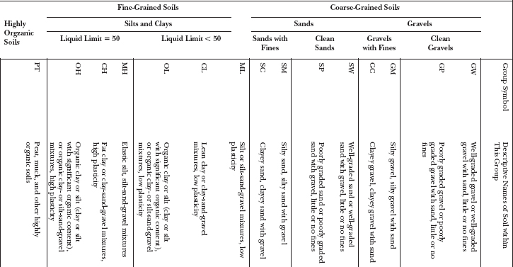
FIGURE 2.2 The Unified Soil Classification System, from ASTM D 2487. The group symbols are a universal set of abbreviations for soil types, as seen for example, in Figure 2.8.
In fine-grained soils, particles are smaller, particle surface area is larger in relation to size and weight, and the spaces between particles, or soil pores, are smaller. As a consequence, surface forces also affect the properties of these soils. The properties of silts are more sensitive to the amount of water in the soil than are those of coarse-grained soils. With sufficient moisture content, capillary forces can reduce friction between particles and change the state of silt from solid to liquid.
Clay particles, being extremely small and flatter in shape, have surface-area-to-volume ratios hundreds or thousands of times greater than even those of silt. Electrostatic repulsive and attractive forces play an important role in clay soil’s properites, as do variations in the arrangement, or fabric, of the particles in sheets or other structures that are more complex than the simple close-packing typical of spherical particles in coarse-grained soils and silts. As a result, clays are generally cohesive, that is, even in the absence of confining force, they retain measurable shear strength. Put simply, cohesive soils tend to stick together. It is often possible to dig vertical-walled excavations in clay soil (Figure 2.4). There is sufficient shear strength in the unconfined soil to prevent the soil wall from sliding into the excavation. In contrast, a cohesionless soil such as sand must be excavated at a much more shallow angle to avoid the collapse of the excavation wall. Cohesive soils also tend to be hard when dry and moldable, or plastic, when moist. Some silts also exhibit cohesive properties, though generally to a lesser extent than clays.
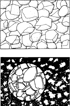
FIGURE 2.3 Silt particles (top) are approximately equidimensional granules, while clay particles (bottom) are platelike and much smaller than silt. (A circular area of clay particles has been magnified to make the structure easier to see.)
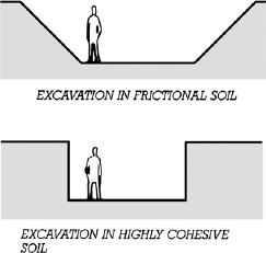
FIGURE 2.4 Excavations in frictional and highly cohesive soils.
Soils for Building Foundations
Generally, soil groups listed toward the top of Figure 2.2 are more desirable for supporting building foundations than those listed further down. The higher-listed soils tend to have better soil engineering properties, that is, they tend to have greater loadbearing capacity, to be more stable, and to react less to changes in moisture content. Rock is generally the best material on which to found a building. When rock is too deep to be reached economically, the designer must choose from the strata of different soils that lie closer to the surface and design a foundation to perform satisfactorily in the selected soil.
Figure 2.5 gives some conservative values of loadbearing capacity for various types of soil. These values give only an approximate idea of the relative strengths of different soils; the strength of any particular soil is also dependent on factors such as the presence or absence of water, the depth at which the soil lies beneath the surface, and, to some extent, the manner in which the foundation acts upon it. In practice, the designer may also choose to reduce the pressure of the foundations on the soil to well below these values in order to reduce the potential for building settlement.
The stability of a soil is its ability to retain its structural properties under the varying conditions that may occur during the lifetime of the building. In general, rock, gravels, and sands tend to be the most stable soils, clays the least stable, and silts somewhere in between. Many clays change size under changing subsurface moisture conditions, swelling considerably as they absorb water and shrinking as they dry. In the presence of highly expansive clay soils, a foundation may need to be designed with underlying void spaces into which the clay can expand to prevent structural damage to the foundation itself. When wet clay is put under pressure, water can be slowly squeezed out of it, with a corresponding gradual reduction in volume. In this circumstance, long-term settlement of a foundation bearing on such soil is a risk that must be considered. Taken together, these properties make many clays the least predictable soils for supporting buildings. (In Figure 2.2, the fine-grained soil groups indicated as having a liquid limit greater than 50 are generally the ones most affected by water content, exhibiting higher plasticity (moldability) and greater expansion when wet and lower strength when dry.
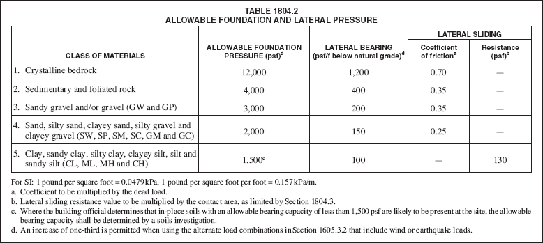
FIGURE 2.5 Presumptive surface bearing values of various soil types, from the 2006 IBC. Classes 3, 4, and 5 refer to the soil group symbols in Figure 2.2. (Portions of this publication reproduce tables from the 2006 International Building Code, International Code Council, Inc., Washington, D.C. Reproduced with Permission. All rights reserved)
In regions of significant earthquake risk, stability of soils during seismic events is also a concern. Sands and silts with high water content are particularly susceptible to liquefaction, that is, a temporary change from solid to liquid state during cyclic shaking. Soil liquefaction can lead to loss of support for a building foundation or excessive pressure on foundation walls.
The drainage characteristics of a soil are important in predicting how water will flow on and under building sites and around building substructures. Where a coarse-grained soil is composed of particles mostly of the same size, it has the greatest possible volume of void space between particles, and water will pass through it most readily. Where coarse-grained soils are composed of particles with a diverse range of sizes, the volume of void space between particles is reduced, and such soils drain water less efficiently. Coarsegrained soils consisting of particles of all sizes are termed well graded or poorly sorted, those with a smaller range of particle sizes are termed poorly graded or well sorted, and those with particles mostly of one size are termed uniformly graded (Figure 2.6).
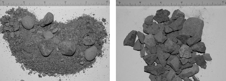
FIGURE 2.6 Two gravel samples, illustrating differences in range of particle sizes or grading. The left-hand sample, with a diverse range of particle sizes, comes from a well-graded sandy gravel. On the right is a sample of a uniformly graded gravel in which there is little variation in size among particles. (Photos by Joseph Iano)
Because of their smaller particle size, fine-grained soils also tend to drain water less efficiently: Water passes slowly through very fine sands and silts and almost not at all through many clays. A building site with clayey or silty soils near the surface drains poorly and is likely to be muddy and covered with puddles during rainy periods, whereas a gravelly site is likely to remain dry. Underground, water passes quickly through strata of gravel and sand but tends to accumulate above layers of clay and fine silt. An excellent way to keep a basement dry is to surround it with a layer of uniformly graded gravel or crushed stone. Water passing through the soil toward the building cannot reach the basement without first falling to the bottom of this porous layer, from where it can be drawn off in perforated pipes before it accumulates (Figures 2.60–2.62). It does little good to place perforated drainage pipes directly in clay or silt because water cannot flow through the impervious soil toward the pipes.
Rarely is the soil beneath a building site composed of a single type. Beneath most buildings, soils of various types are arranged in superimposed layers (strata) that were formed by various past geologic processes. Frequently, soils in any one layer are themselves also mixtures of different soil groups, bearing descriptions such as well-graded gravel with silty clay and sand, poorly graded sand with clay, lean clay with gravel, and so on. Determining the suitability of any particular site’s soils for support of a building foundation, then, depends on the behaviors of the various soils types and how they interact with each other and with the building foundation.
Subsurface Exploration and Soils Testing
Prior to designing a foundation for any building larger than a single-family house (and even for some single-family houses), it is necessary to determine the soil and water conditions beneath the site. This can be done by digging test pits or by making test borings. Test pits are useful when the foundation is not expected to extend deeper than roughly about 16 feet (3 m), the maximum practical reach of small excavating machines. The strata of the soil can be observed in the pit, and soil samples can be taken for laboratory testing. The level of the water table (the elevation at which the soil is saturated and the pressure of the groundwater is atmospheric) will be readily apparent in coarse-grained soils if it falls within the depth of the pit because water will seep through the walls of the pit up to the level of the water table. On the other hand, if a test pit is excavated below the water table in clay, free water will not seep into the pit because the clay is relatively impermeable. In this case, the level of the water table must be determined by means of an observation well or special devices that are installed to measure water pressure. If desired, a load test can be performed on the soil in the bottom of a test pit to determine the stress the soil can safely carry and the amount of settlement that should be anticipated under load.
If a pit is not dug, borings with standard penetration tests can give an indication of the bearing capacity of the soil by the number of blows of a standard driving hammer required to advance a sampling tube into the soil by a fixed amount. Laboratory-quality soil samples can also be recovered for testing. Test boring (Figure 2.7) extends the possible range of exploration much deeper into the earth than test pits and returns information on the thickness and locations of the soil strata and the depth of the water table. Usually, a number of holes are drilled across the site; the information from the holes is coordinated and interpolated in the preparation of drawings that document the subsurface conditions for the use of the engineer who will design the foundation (Figure 2.8).
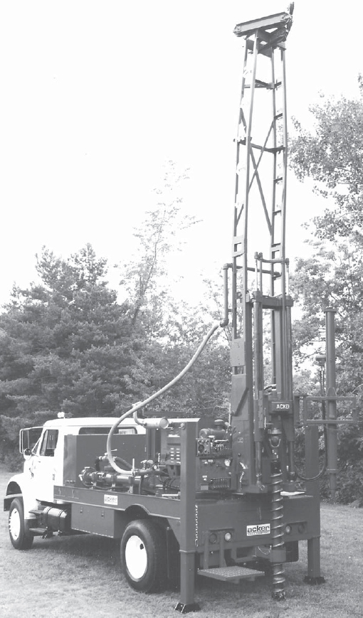
FIGURE 2.7 A truck-mounted drilling rig capable of core drilling to 1500 feet (450 m). (Courtesy of Acker Drilling Company, Inc.)
Laboratory testing of soil samples is important for foundation design. By passing a dried sample of coarse-grained soil through a set of sieves with graduated mesh sizes, the particle size distribution in the soil can be determined. Further tests on fine-grained soils assist in their identification and provide information on their engineering properties. Important among these are tests that establish the liquid limit, the water content at which the soil passes from a plastic state to a liquid state, and the plastic limit, the water content at which the soil loses its plasticity and begins to behave as a solid. Additional tests can determine the water content of the soil, its permeability to water, its shrinkage when dried, its shear and compressive strengths, the amount by which the soil can be expected to consolidate under the load, and the rate at which consolidation will take place (Figure 2.9). The last two qualities are helpful in predicting the rate and magnitude of foundation settlement in a building.
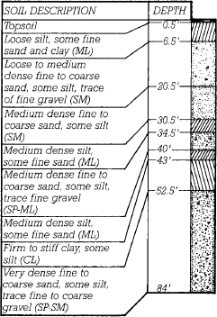
FIGURE 2.8 A typical log from a soil test boring indicating the type of soil in each stratum and the depth in feet at which it was found. The abbreviations in parentheses refer to the Unified Soil Classification System, and are explained in Figure 2.2.
The information gained through subsurface exploration and soil testing is summarized in a written geotechnical report. This report includes the results of both the field tests and the laboratory tests, recommended types of foundations for the site, recommended depths and bearing stresses for the foundations, and an estimate of the expected rate of foundation settlement. This information can be used directly by foundation and structural engineers in the design of the excavations, dewatering and slope support systems, foundations, and substructure. It is also used by contractors in the planning and execution of sitework.
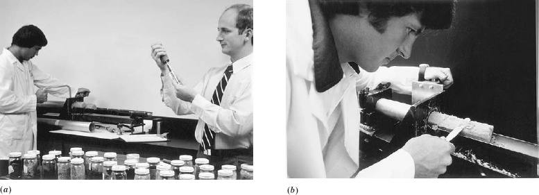
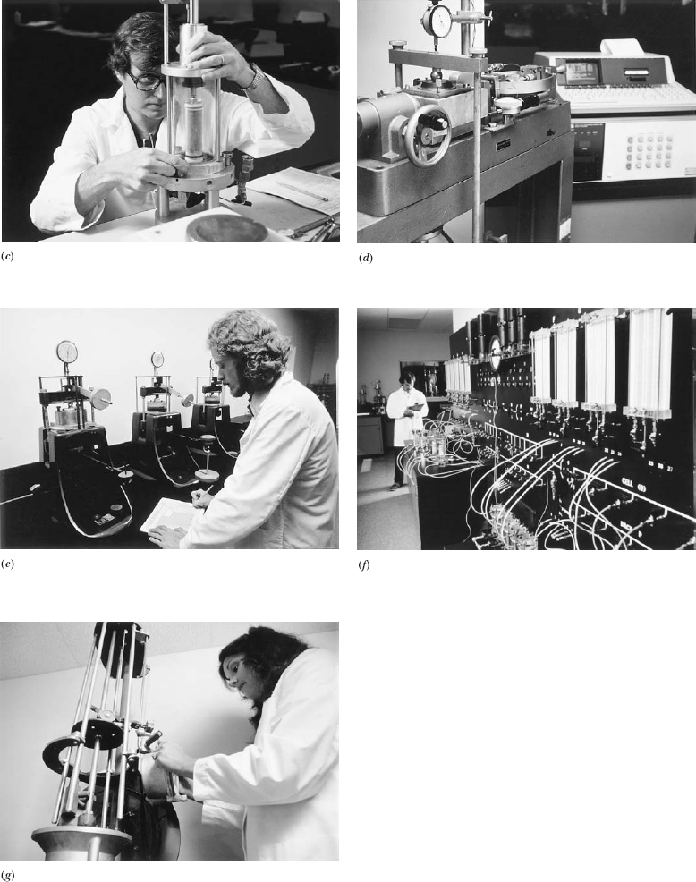
FIGURE 2.9 Some laboratory soil testing procedures. (a) To the right, the hardness of split spoon samples is checked with a penetrometer to be sure that they come from the same stratum of soil. To the left, a soil sample from a Shelby sampling tube is cut into sections for testing. (b) A section of undisturbed soil from a Shelby tube is trimmed to examine the stratification of silt and clay layers. (c) A cylindrical sample of soil is set up for a triaxial load test, the principal method for determining the shear strength of soil. The sample will be loaded axially by the piston in the top of the apparatus and also circumferentially by water pressure in the transparent cylinder. (d) A direct shear test, used to measure the shear strength of cohesionless soils. A rectangular prism of soil is placed in a split box and sheared by applying pressure in opposite directions to the two halves of the box. (e) One-dimensional consolidation tests in progress on fine-grained soils to determine their compressibility and expected rate of settlement. Each sample is compressed over an extended period of time to allow water to flow out of the sample. (f) A panel for running 30 simultaneous constant-head permeability tests to determine the rate at which a fluid, usually water, moves through a soil. (g) A Proctor compaction test, in which successive layers of soil are compacted with a specified tamping force. The test is repeated for the same soil with varying moisture content, and a curve is plotted of density achieved versus moisture content of the soil to identify the optimum moisture content for compacting the soil in the field. Not shown here are some common testing procedures for grain size analysis, liquid limit, plastic limit, specific gravity, and unconfined compression. (Courtesy of Ardaman and Associates, Inc., Orlando, Florida)
CONSIDERATIONS OF SUSTAINABILITY IN SITE WORK, EXCAVATIONS, AND FOUNDATIONS
Building sites should be selected and developed so as to protect and conserve natural habitats and resources, to promote biodiversity, to preserve quality open space, and to minimize pollution and unnecessary energy consumption.
Site Selection
Buying and renovating an existing building rather than building a new one saves a great deal of building material and energy. If the existing building has been scheduled for demolition, its renovation also avoids the disposal of an enormous quantity of material in a landfill.
Building in an urban area with existing infrastructure, rather than in undeveloped land unconnected to other community resources, protects open space, natural habitats, and natural resources.
Building on a damaged or polluted site, and designing the building so that it helps to restore the site, benefits the environment rather than degrades it.
Avoiding construction on prime agricultural land prevents the permanent loss of this productive use of the land.
Avoiding construction on undeveloped land that is environmentally sensitive protects the wildlife and natural habitats such land supports. This includes floodplains, land that provides habitat for endangered or threatened species, wetlands, mature forest lands and prairies, and land adjacent to natural bodies of water.
Avoiding construction on public parkland or land adjacent to bodies of water that support recreational use prevents the permanent loss of public resources.
Selecting a building that is well connected to existing networks of public transportation, and to pedestrian and bicycle paths, pays environmental dividends every day for the life of the building by saving fuel, reducing air pollution from automobiles, and minimizing commute times.
Site Design
Minimizing the building footprint and protecting and enhancing portions of the site with natural vegetation protects habitat and helps maintain biodiversity.
Appropriate landscape design and the use of captured rainwater, recycled wastewater, or other nonpotable sources of water for landscape irrigation minimize wasteful water consumption.
Minimizing impervious ground surface (such as for vehicle parking) and providing a surface drainage system that conducts water to areas on the site where it can be absorbed into the ground works to replenish natural aquifers, avoid overloading of storm sewer systems, and reduce water pollution.
Grading the site to appropriate slopes and planting vegetation that holds the soil in place will prevent erosion.
Large existing trees cannot be replaced except by growing new ones over a period of many decades. Planting of new trees is good, but preservation of existing trees is even better.
Distinctive site features such as rock formations, forests, grasslands, streams, marshes, and recreational paths and facilities, if destroyed for new construction, can never be replaced.
Providing shade, vegetated or reflective roof surfaces, reflective paving materials, and open pavement systems reduces heat island effects and creates an improved microclimate for both humans and wildlife.
Minimizing nighttime light pollution is a benefit to humans and nocturnal wildlife.
Avoiding unnecessary shading of adjacent buildings protects those buildings’ sources of natural illumination and useful solar heat, minimizing their unnecessary consumption of electricity and heating fuel.
Siting a building for best exposure to sun and wind maximizes solar heat gain in winter and minimizes it in summer to save heating and air conditioning fuel. It also allows utilization of daylight to replace electric lighting.
In general, a building should be designed in such a manner that the site does the heaviest work of environmental modification through good orientation to sun and wind, trees that are placed so as to provide shade and windbreaks, and use of below-grade portions of the building for thermal mass. The passive shell of the building can do most of the rest of the work through orientation of windows with respect to sunlight, good thermal insulation and airtightness, utilization of thermal mass, and energy-efficient windows. The active heating, cooling, and lighting equipment should serve only to fine-tune the interior environment, using as little fossil fuel and electricity as possible.
Construction Process
It is essential to protect trees and sensitive areas of the site from damage during construction.
A building should comply with all local conservation laws relating to soils, wetlands, and stormwater.
Topsoil should be stockpiled carefully during construction and reused on the site.
It is important to guard against soil erosion by water and wind during construction, as well as the sedimentation of streams and sewers, or the polluting of air with dust or particulates that can result.
Vehicle tires compact soil so that it cannot absorb water or support vegetation. Thus, it is important to develop minimal, well-marked access routes for trucks and construction machinery that minimize soil compaction, as well as minimizing noise, dust, air pollution, and inconvenience to neighboring buildings and sites.
Construction machinery should be selected and maintained so that it pollutes the air as little as possible.
Surplus excavated soils should be reused either on the site or on another site nearby.
Construction wastes should be recycled as much as possible.
EXCAVATION
At least some excavation is required for every building. Organic topsoil is subject to decomposition and to shrinking and swelling with changes in moisture content. It is excellent for growing lawns and landscape plants but unsuitable for supporting buildings. Often, it is scraped away from the building area and stockpiled to one side for redistribution over the site after construction of the building is complete. After the topsoil has been removed, further digging is necessary to place the footings out of reach of water and wind erosion. In colder climates, foundations must be placed below the level to which the ground freezes in winter, the frost line, or they must be insulated in such a way that the soil beneath them cannot freeze. Otherwise, a foundation can be lifted and damaged by soil that expands slightly as it freezes. Or, under certain soil and temperature conditions, upward migration of water vapor from the pores in the soil can result in the formation of ice lenses, thick layers of frozen water crystals than can lift foundations by even larger amounts.
Excavation is required on many sites to place the footings at a depth where soil of the appropriate bearing capacity is available. Excavation is frequently undertaken so that one or more levels of basement space can be added to a building, whether for additional habitable rooms, for parking, or for mechanical equipment and storage. Where footings must be placed deep to get below the frost line or reach competent soil, a basement is often bargain-rate space, adding little to the overall cost of the building.
In particulate soils, a variety of excavating machines can be used to loosen and lift the soil from the ground: bulldozers, shovel dozers, backhoes, bucket loaders, scrapers, trenching machines, and power shovels of every type. If the soil must be moved more than a short distance, dump trucks come into use.
In rock, excavation is slower and many times more costly. Weak or highly fractured rock can sometimes be broken up with power shovels, tractor-mounted rippers, pneumatic hammers, or drop balls such as those used in building demolition. Blasting, in which explosives are placed and detonated in lines of closely spaced holes drilled deep into the rock, is often necessary. In developed areas where blasting is impractical, rock can be broken up with hydraulic splitters.
Excavation Support
If the site is sufficiently larger than the area to be covered by the building, the edges of the excavation can be sloped back or benched at an angle such that the soil will not slide back into the hole. This angle, called the angle of repose, can be steep for cohesive soils such as the stiffer clays, but it must be shallow for frictional soils such as sand and gravel. On constricted sites, the soil surrounding an excavation must be held back by some kind of slope support or excavation support capable of resisting the pressures of earth and groundwater (Figure 2.10). Such construction can take many forms, depending on the qualities of the soil, depth of excavation, equipment and preferences of the contractor, proximity of surrounding buildings, and level of the water table.
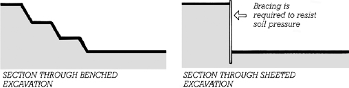
FIGURE 2.10 On a spacious site, an excavation can be benched. When excavating close to property lines or nearby buildings, some form of slope support, such as sheeting, is used to retain the soil around the excavation.
Shoring
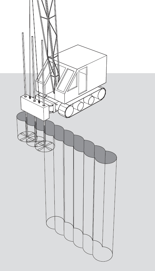
The most common types of slope support, or shoring, are soldier beams and lagging, and sheet piling. With soldier beams and lagging, steel columns called H-piles or soldier beams are driven vertically into the earth at small intervals around an excavation site before digging begins. As earth is removed, the lagging, usually consisting of heavy wood planks, is placed against the flanges of the columns to retain the soil outside the excavation (Figures 2.11 and 2.12). Sheet piling or sheeting consists of vertical planks of wood, steel, or precast concrete that are placed tightly against one another and driven into the earth to form a solid wall before excavation begins (Figures 2.13 and 2.14). Most often, shoring is temporary, and it is removed as soil is replaced in the excavation. However, it may also be left in place to become a permanent part of the building’s substructure. This may be necessary, for example, where shoring is located extremely close to a property line and there is no practical way to remove it after completion of construction without disturbing adjacent property or structures.
FIGURE 2.11 Soldier beams and lagging, seen in horizontal section.
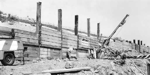
FIGURE 2.12 Soldier beams and lagging. Lagging planks are added at the bottom as excavation proceeds. The drill rig is boring a hole for a tieback to brace a soldier beam. (Courtesy of Fr anki Foundation Company)
Slope support may also take the form of pneumatically applied concrete, also called shotcrete, in which excavation proceeds first and then the sloped sides are reinforced with a relatively stiff concrete mixture sprayed directly from a hose onto the soil. This method works well where the soil is sufficiently cohesive to hold a steep slope at least temporarily. The hardened concrete reinforces the slope and protects against soil erosion. (Figure 2.15).
Slurry Walls
A slurry wall is a more complicated and expensive form of excavation support that is usually economical only if it becomes part of the permanent foundation of the building. The first steps in creating a slurry wall are to lay out the wall’s location on the surface of the ground with surveying instruments and to define the location and thickness of the wall with shallow poured concrete guiide walls (Figures 2.16 and 2.17). When the formwork has been removed from the guide walls, a special narrow clamshell bucket, mounted on a crane, is used to excavate the soil from between the guide walls. As the narrow trench deepens, the tendency of its earth walls to collapse is counteracted by filling the trench with a viscous mixture of water and bentonite clay, called a slurry, which exerts pressure against the earth walls, holding them in place. The clamshell bucket is lowered and raised through the slurry to continue excavating the soil from the bottom of the trench until the desired depth has been reached, often a number of stories below the ground. Slurry is added as required to keep the trench full at all times.
Meanwhile, workers have welded together cages of steel bars designed to reinforce the concrete wall that will replace the slurry in the trench. Steel tubes whose diameter corresponds to the width of the trench are driven vertically into the trench at predetermined intervals to divide it into sections of a size that can be reinforced and concreted conveniently. The concreting of each section begins with the lowering of a cage of reinforcing bars into the slurry. Then concrete is poured into the trench from the bottom up, using a funnel-and-tube arrangement called a tremie. As the concrete rises in the trench, it displaces the slurry, which is pumped out into holding tanks, where it is stored for reuse. After the concrete reaches the top of the trench and has hardened sufficiently, the vertical pipes on either side of the recently poured section are withdrawn from the trench, and the adjoining sections are poured. This process is repeated for each section of the wall. When the concrete in all the trenches has cured to its intended strength, earth removal begins inside the wall, which serves as sheeting for the excavation.
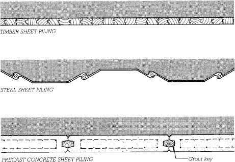
FIGURE 2.13 Horizontal sections through three types of sheet piling. The shading represents the retained earth.
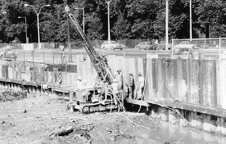
FIGURE 2.14 Drilling tieback holes for a wall of steel sheet piling. Notice the completed tieback connections to the horizontal waler in the foreground. The hole in the top of each piece of sheet piling allows it to be lifted by a crane. (Courtesy of Franki Foundation Company)
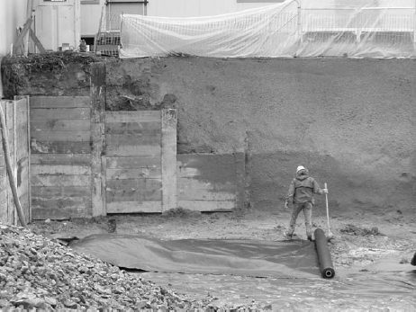
FIGURE 2.15 Where slope support turns the corner in this excavation and the soil can be sloped at a lesser angle, less expensive shotcrete takes the place of soldier beams and lagging. (Photo by Joseph Iano)
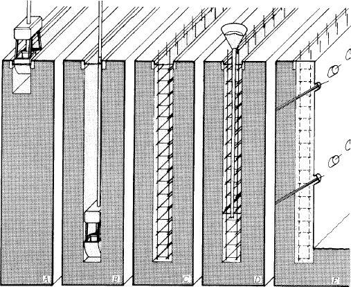
FIGURE 2.16 Steps in constructing a slurry wall. (a) The concrete guide walls have been installed, and the clamshell bucket begins excavating the trench through a bentonite clay slurry. (b) The trench is dug to the desired depth, with the slurry serving to prevent collapse of the walls of the trench. (c) A welded cage of steel reinforcing bars is lowered into the slurry. (d) The trench is concreted from the bottom up with the aid of a tremie. The displaced slurry is pumped from the trench, filtered, and stored for reuse. (e) The reinforced concrete wall is tied back as excavation progresses.
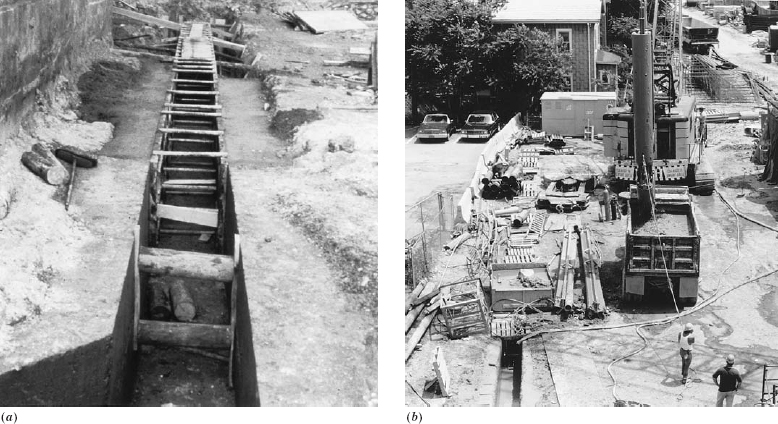
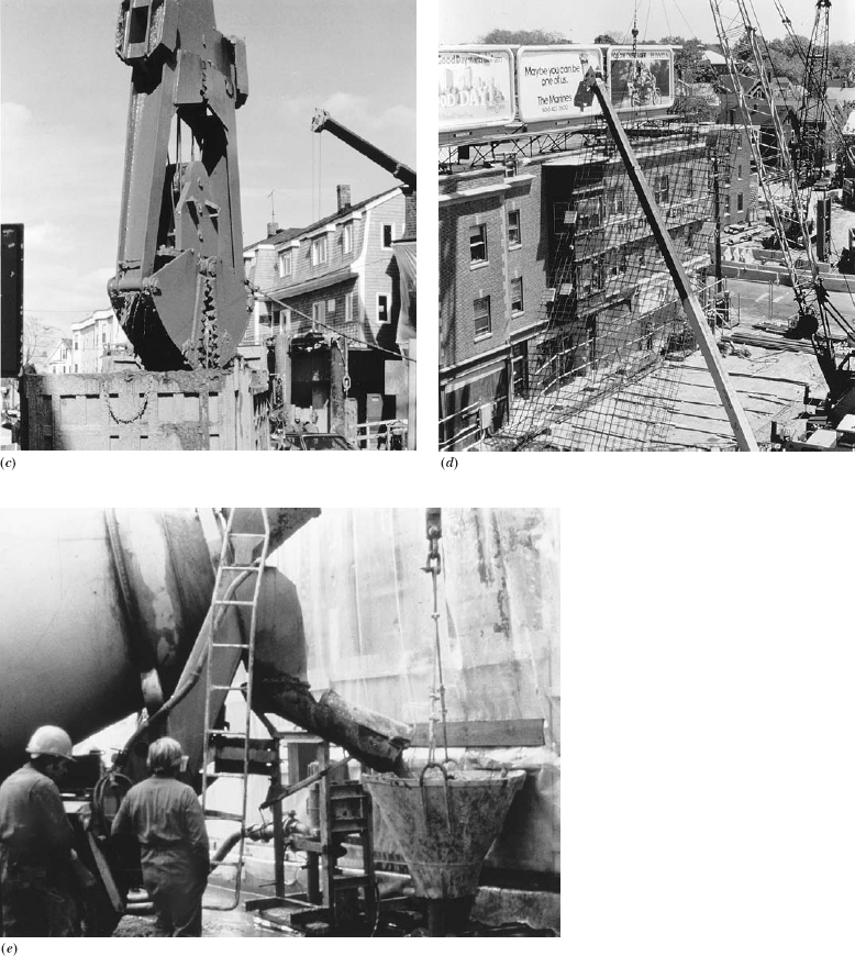
FIGURE 2.17 Constructing a slurry wall. (a) The guide walls are formed and poured in a shallow trench. (b) The narrow clamshell bucket discharges a load of soil into a waiting dump truck. Most of the trench is covered with wood pallets for safety. (c) A detail of the narrow clamshell bucket used for slurry wall excavation. (d) Hoisting a reinforcing cage from the area where it was assembled, getting ready to lower it into the trench. The depth of the trench and height of the slurry wall are equal to the height of the cage, which is about four stories for this project. (e) Concreting the slurry wall with a tremie. The pump just to the left of the tremie removes slurry from the trench as concrete is added. (Photos b, c, and d courtesy of Franki Foundation Company. Photos a and e courtesy of Soletanche)
In addition to the sitecast concrete slurry wall described in the preceding paragraphs, precast concrete slurry walls are built. The wall is prestressed and is produced in sections in a precasting plant (see Chapter 15), then trucked to the construction site. The slurry for precast walls is a mixture of water, bentonite clay, and portland cement. Before a section is lowered by a crane into the slurry, its face is coated with a compound that prevents the clay–cement slurry from adhering to it (Figure 2.18). The sections are installed side by side in the trench, joined by tongue-and-groove edges or synthetic rubber gaskets. After the portland cement has caused the slurry to harden to a soillike consistency, excavation can begin, with the hardened slurry on the inside face of the wall dropping away from the coated surface as soil is removed. The primary advantages of a precast slurry wall over a sitecast one are better surface quality, more accurate wall alignment, a thinner wall (due to the structural efficiency of prestressing), and improved watertightness of the wall because of the continuous layer of solidified clay outside.
Soil Mixing
Soil mixing is a technique of adding a modifying substance to soil and blending it in place by means of augers or paddles rotating on the end of a vertical shaft (Figure 2.19). This technique has several applications, one of which is to remediate soil contaminated with a chemical or biological substance by blending it with a chemical that renders it harmless. Another is to mix portland cement and water with a soil to create a cylinder of low-strength concrete in the ground. A linear series of these cylinders can serve as a cutoff wall against water penetration or as excavation support (Figure 2.20). Soil mixing can also serve to stabilize and strengthen areas of weak soil.
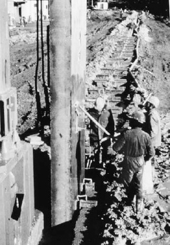
FIGURE 2.18 Workers apply a nonstick coating to a section of precast concrete slurry wall as it is lowered into the trench.
Bracing
All forms of slope support and excavation support must be braced against soil and water pressures as the excavation deepens (Figure 2.21). Crosslot bracing utilizes temporary steel wide-flange columns that are driven into the earth by a piledriver at points where braces will cross. As the earth is excavated down around the sheeting and the columns, tiers of horizontal bracing struts, usually of steel, are added to support walers, which are beams that span across the face of the sheeting. Where the excavation is too wide for crosslot bracing, sloping rakers are used instead, bearing against heel blocks or other temporary footings.
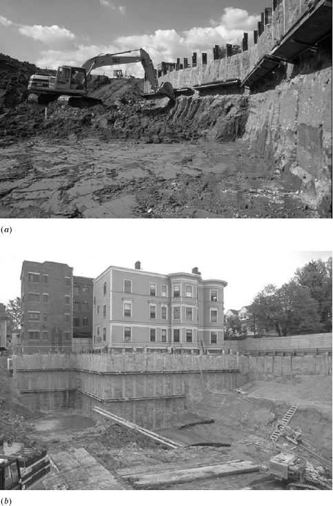
FIGURE 2.20 Soil-mixed excavation support. (a) Excavation proceeds after completion of soil mixing. Bracing consists of soldier piles, walers, and tiebacks. The soldier piles are inserted during soil mixing, before the soil/cement mixture hardens. The walers and tiebacks are installed later, as excavation progresses. (b) Fully excavated soil-mixed sheeting. This excavation support system must be strong enough to resist the soil pressures caused by the adjacent buildings. (Photographs courtesy of Schnable Foundation Company)
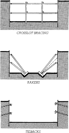
FIGURE 2.21 Three methods of bracing shoring drawn in cross section. The connection between the waler and the brace, raker, or tieback needs careful structural design. The broken line between rakers indicates the mode of excavation: The center of the hole is excavated first with sloping sides, as indicated by the broken line. The heel blocks and uppermost tier of rakers are installed. As the sloping sides are excavated deeper, more tiers of rakers are installed. Notice how the tiebacks leave the excavation totally free of obstructions.
Both rakers and crosslot bracing, especially the latter, are a hindrance to the excavation process. A clamshell bucket on a crane must be used to remove the earth between the braces, which is much less efficient and more costly than removing soil with a shovel dozer or backhoe in an open excavation.
Where subsoil conditions permit, tiebacks can be used instead of braces to support the sheeting while maintaining an open excavation. At each level of walers, holes are drilled at intervals through the sheeting and the surrounding soil into rock or a stratum of stable soil. Steel cables or tendons are then inserted into the holes, grouted to anchor them to the rock or soil, and stretched tight with hydraulic jacks (posttensioned) before they are fastened to the walers (Figures 2.22–2.24).
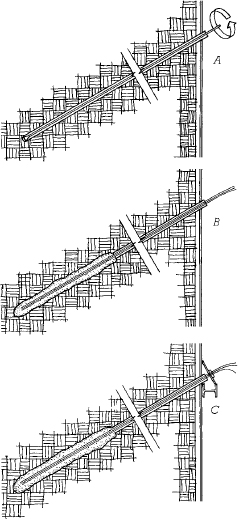
FIGURE 2.22 Three steps in the installation of a tieback to a soil anchor. (a) A rotary drill bores a hole through the sheeting and into stable soil or rock. A steel pipe casing keeps the hole from caving in where it passes through noncohesive soils. (b) Steel prestressing tendons are inserted into the hole and grouted under pressure to anchor them to the soil. (c) After the grout has hardened, the tendons are tensioned with a hydraulic jack and anchored to a waler.
Excavations in fractured rock can often avoid sheeting altogether, either by injecting grout into the joints of the rock to stabilize it or by drilling into the rock and inserting rock anchors that fasten the blocks together (Figure 2.25).
In some cases, vertical walls of particulate soils can be stabilized by soil nailing. A soil nail is similar to a rock anchor: It is a length of steel reinforcing bar that is inserted into a nearly horizontal hole drilled deep into the soil. Grout is injected into the hole to bind the soil nail to the surrounding soil. Large numbers of closely spaced nails are used to knit a large block of soil together so that it behaves more like weak rock than particulate soil.
Bracing and tiebacks in excavations are usually temporary. Their function is taken over permanently by the floor structure of the basement levels of the building, which is designed specifically to resist lateral loads from the surrounding earth as well as ordinary floor loads.
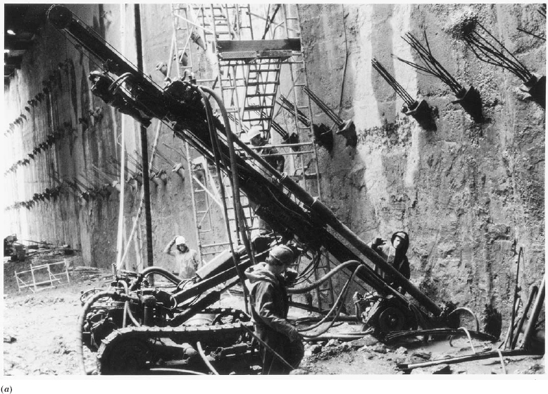
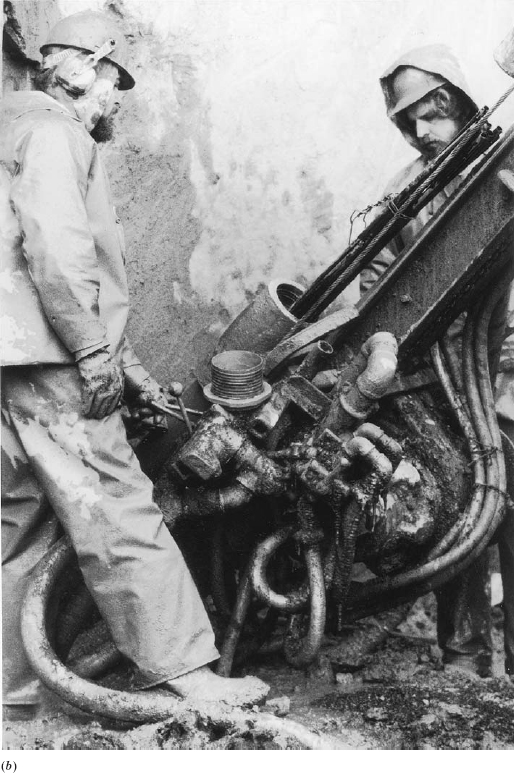
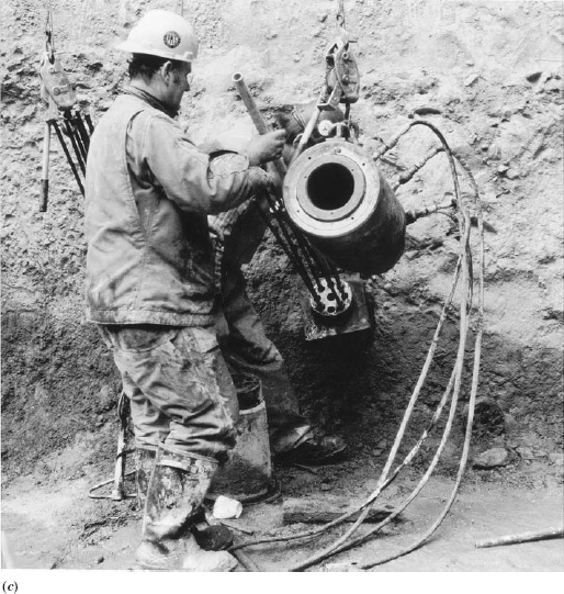
FIGURE 2.23 Installing tiebacks. (a) Drilling through a slurry wall for a tieback. The ends of hundreds of completed tiebacks protrude from the wall. (b) Inserting prestressing tendons into the steel casing for a tieback. The apparatus in the center of the picture is for pressure injecting grout around the tendons. (c) After the tendons have been tensioned, they are anchored to a steel chuck that holds them under stress, and the cylindrical hydraulic jack is moved to the next tieback. (Photos courtesy of Franki Foundation Company)
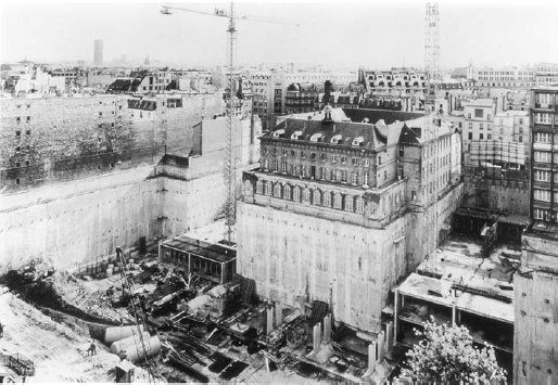
FIGURE 2.24 Slurry wall and tieback construction used to support historic buildings around a deep excavation for a station of the Paris Metro. (Photo courtesy of Soletanche)
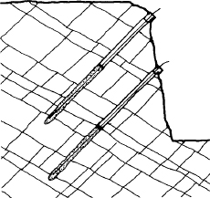
FIGURE 2.25 Rock anchors are similar to tiebacks but are used to hold jointed rock formations in place around an excavation.
Dewatering
During construction, excavations must be kept free of standing water. Such water may come from precipitation or it may come from groundwater seepage originating from any of a number of sources, such as surface water percolating through the soil, underground streams, perched water moving over impervious soil strata, or adjacent permanently saturated soil areas where the excavation extends below the water table. Some shallow excavations in relatively dry soil conditions may remain free of standing water without any intervention. But most excavations require some form of dewatering, or extraction of water from the excavation or surrounding soil. The most common method of dewatering is to remove water by pumping as it accumulates in pits, called sumps, created at low points in the excavation. Where the volume of groundwater flowing into the excavation is great, or with certain types of soils, particularly sands and silt, that may be softened by constant seepage, it may be necessary to keep groundwater from entering the excavation at all. This can be done either by pumping water from the surrounding soil to depress the water table below the level of the bottom of the excavation or by erecting a watertight barrier, such as a slurry wall, around the excavation (Figure 2.26).
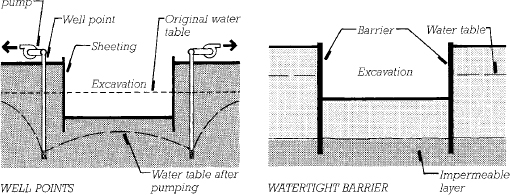
FIGURE 2.26 Two methods of keeping an excavation dry, viewed in cross section. The water sucked from well points depresses the water table in the immediate vicinity to a level below the bottom of the excavation. Watertight barrier walls work only if their bottom edges are inserted into an impermeable stratum that prevents water from working its way under the walls.
Well points are commonly used to depress the water table. These are vertical sections of pipe with screened openings at the bottom that keep out soil particles while allowing water to enter. Closely spaced well points are driven into the soil around the entire perimeter of the excavation. These are connected to horizontal header pipes leading to pumps that continually draw water from the system and discharge it away from the building site. Once pumping has drawn down the water table in the area of the excavation, work can continue “in the dry” (Figures 2.27 and 2.28). For excavations deeper than the 20 feet (6 m) or so that cannot be drained by a suction pump stationed at ground level, two rings of well points may be required, the inner ring being driven to a deeper level than the outer ring, or a single ring of deep wells with submersible force pumps may have to be installed.
In some cases, well points may not be practical: they may have insufficient capacity to ensure that an excavation remains dry; restrictions on the disposal of groundwater may limit their use; reliability due to power outages may be a concern; or lowering of the water table may have serious adverse effects on neighboring buildings by causing consolidation and settling of soil under their foundations or by exposing untreated wood foundation piles, previously protected by total immersion in water, to decay. In these cases, a watertight barrier wall may be used as an alternative (Figure 2.26). Slurry walls and soil mixed walls (pages 40–45) can make excellent watertight barriers. Sheet piling can also work, but it tends to leak at the joints. Soil freezing is also possible. In this method, an array of vertical pipes similar to well points is used to continuously circulate coolant at temperatures low enough to freeze the soil around an excavation area, resulting in a temporary but reliable barrier to groundwater. Watertight barriers must resist the hydrostatic pressure of the surrounding water, which increases with depth, so for deeper excavations, a system of bracing or tiebacks is required. A watertight barrier also works only if it reaches into a stratum of impermeable soil such as clay. Otherwise, water can flow beneath the barrier and rise up into the excavation.
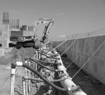
FIGURE 2.27 Well point dewatering. Closely spaced vertical well points connect to the larger-diameter header pipe. (Courtesy of Griffin Dewatering Corporation)
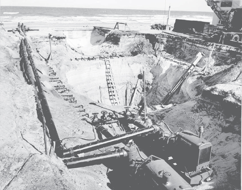
FIGURE 2.28 An excavation is kept dry despite the close proximity of a large body of water. Two dewatering pumps are visible in the foreground. A pair of header pipes and numerous well points can be seen surrounding the excavation. (Courtesy of Griffin Dewatering Corporation)
FOUNDATIONS
It is convenient to think of a building as consisting of three major parts: the superstructure, which is the above-ground portion of the building; the substructure, which is the habitable below-ground portion; and the foundations, which are the components of the building that transfer its loads into the soil (Figure 2.29).
There are two basic types of foundations: shallow and deep. Shallow foundations are those that transfer the load to the earth at the base of the column or wall of the substructure. Deep foundations, either piles or caissons, penetrate through upper layers of incompetent soil in order to transfer the load to competent bearing soil or rock deeper within the earth. Shallow foundations are generally less expensive than deep ones and can be used where suitable soil is found at the level of the bottom of the substructure, whether this be several feet or several stories below the ground surface.
The primary factors that affect the choice of a foundation type for a building are:
• Subsurface soil and groundwater conditions
• Structural requirements, including foundation loads, building configurations, and depth
Secondary factors that may be important include:
• Construction methods, including access and working space
• Environmental factors, including noise, traffic, and disposal of earth and water
• Building codes and regulations
• Proximity of adjacent property and potential impacts on that property
• Time available for construction
• Construction risks
The foundation engineer is responsible for assessing these factors and, working together with other members of the design and construction team, selecting the most suitable foundation system.
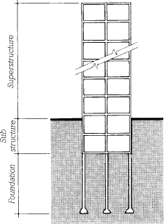
FIGURE 2.29 Superstructure, substructure, and foundation. The substructure in this example contains two levels of basements, and the foundation consists of bell caissons. (In some buildings, the substructure and foundation may be partly or wholly the same.)
Shallow Foundations
Most shallow foundations are simple concrete footings. A column footing is a square block of concrete, with or without steel reinforcing, that accepts the concentrated load placed on it from above by a building column and spreads this load across an area of soil large enough that the allowable bearing stress of the soil is not exceeded. A wall footing or strip footing is a continuous strip of concrete that serves the same function for a loadbearing wall (Figures 2.30 and 2.31).
To minimize settlement, footings are usually placed on undisturbed soil. Under some circumstances, footings may be constructed over engineered fill, which is earth that has been deposited under the supervision of a soils engineer. The engineer, working from the results of laboratory compaction tests on samples taken from the soil used for filling, makes sure that the soil is deposited in thin layers at a controlled moisture content and compacted in accordance with detailed procedures that ensure a known loadbearing capacity and long-term stability.
Footings appear in many forms in different foundation systems. In climates with little or no ground frost, a concrete slab on grade with thickened edges is the least expensive foundation and floor system that one can use and is applicable to one- and two-story buildings of any type of construction (see Chapter 14 for further information on slabs on grade). Or, in colder regions the edges of a slab on grade may be supported with deeper wall footings that bear on soil below the frost line. For floors raised above the ground, either over a crawlspace or a basement, support is provided by concrete or masonry foundation walls supported on concrete strip footings (Figure 2.32). When building on slopes, it is often necessary to step the footings to maintain the required depth of footing at all points around the building (Figure 2.33). If soil conditions or earthquake precautions require it, column footings on steep slopes may be linked together with reinforced concrete tie beams to avoid possible differential slippage between footings.
Footings cannot legally extend beyond a property line, even for a building built tightly against it. If the outer toe of the footing were simply cut off at the property line, the footing would not be symmetrically loaded by the column or wall and would tend to rotate and fail. Combined footings and cantilever footings solve this problem by tying the footings for the outside row of columns to those of the next row in such a way that any rotational tendency is neutralized (Figure 2.34).
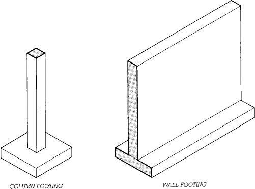
FIGURE 2.30 A column footing and a wall footing of concrete. The steel reinforcing bars have been omitted from this illustration for clarity. The role of steel reinforcing in the structural performance of concrete elements is explained in Chapter 13.
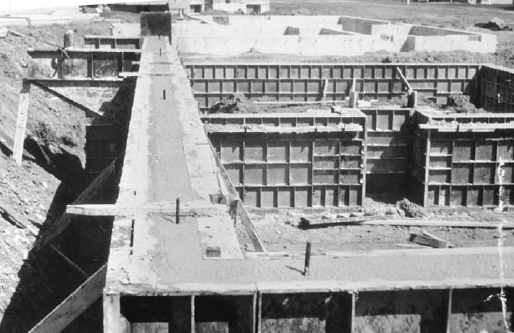
FIGURE 2.31 These concrete foundation walls for an apartment building, with their steel formwork not yet stripped, rest on wall footings. For more extensive illustrations of wall and column footings, see Figures 14.5, 14.7, and 14.11, and 14.13 (Reprinted with permission of the Portland Cement Association from Design and Control of Concrete Mixtures; Photos: Portland Cement Association, Skokie, IL)
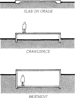
FIGURE 2.32 Three types of substructures with shallow foundations. The slab on grade is the most economical under many circumstances, especially where the water table lies near the surface of the ground. A crawlspace is often used under a floor structure of wood or steel, and gives much better access to underfloor piping and wiring than a slab on grade. Basements provide usable space for building occupants.
In situations where the allowable bearing capacity of the soil is low in relation to the weight of the building, column footings may become large enough that it is more economical to merge them into a single mat or raft foundation that supports the entire building. Mats for very tall buildings may be 6 feet (1.8 m) thick or more and are heavily reinforced (Figure 2.35).
Where the bearing capacity of the soil is low and settlement must be carefully controlled, a floating foundation is sometimes used. A floating foundation is similar to a mat foundation, but is placed beneath a building at a depth such that the weight of the soil removed from the excavation is equal to the weight of the building above. One story of excavated soil weighs about the same as five to eight stories of superstructure, depending on the density of the soil and the construction of the building (Figure 2.36).
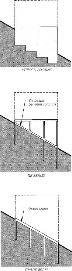
FIGURE 2.33 Foundations on sloping sites, viewed in a cross section through the building. The broken line indicates the outline of the superstructure. Wall footings are stepped to maintain the necessary distance between the bottom of the footing and the surface of the ground. Separate column foundations, whether caissons, as shown here, or column footings, are often connected with reinforced concrete tie beams to reduce differential movement between the columns. A grade beam differs from a tie beam by being reinforced to distribute the continuous load from a bearing wall to separate foundations.
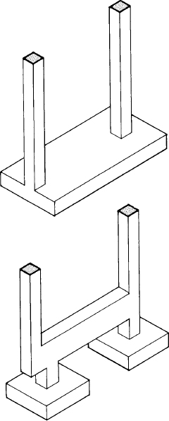
FIGURE 2.34 Either a combined footing (top) or a cantilevered footing (bottom) is used when columns must abut a property line. By combining the foundation for the column against the property line, at the left, with the foundation for the next interior column to the right in a single structural unit, a balanced footing design can be achieved. The concrete reinforcing steel has been omitted from these drawings for the sake of clarity.
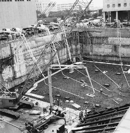
FIGURE 2.35 Pouring a large foundation mat. Six truck-mounted pumps receive concrete from a continuous procession of transit-mix concrete trucks and deliver this concrete to the heavily reinforced mat. Concrete placement continues nonstop around the clock until the mat is finished to avoid “cold joints,” weakened planes between hardened concrete and fresh concrete. The soil around this excavation is supported with a sitecast concrete slurry wall. Most of the slurry wall is tied back, but a set of rakers is visible at the lower right. (Courtesy of Schwing America, Inc.)
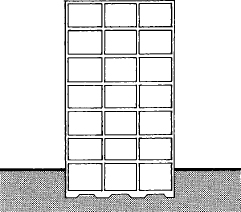
FIGURE 2.36 A cross section through a building with a floating foundation. The building weighs approximately the same as the soil excavated for the substructure, so the stress in the soil beneath the building is the same after construction as it was before.
Deep Foundations
Caissons
A caisson, or drilled pier (Figure 2.37), is similar to a column footing in that it spreads the load from a column over a large enough area of soil that the allowable stress in the soil is not exceeded. It differs from a column footing in that it extends through strata of unsatisfactory soil beneath the substructure of a building until it reaches a more suitable stratum. A caisson is constructed by drilling or hand-digging a hole, belling (flaring) the hole out at the bottom as necessary to achieve the required bearing area, and filling the hole with concrete. Large auger drills (Figures 2.38 and 2.39) are used for drilling caissons; hand excavation is used only if the soil is too full of boulders for the drill. A temporary cylindrical steel casing is usually lowered around the drill as it progresses to support the soil around the hole. When a firm bearing stratum is reached, the bell, if required, is created at the bottom of the shaft either by hand excavation or by a special belling bucket on the drill (Figure 2.40). The bearing surface of the soil at the bottom of the hole is then inspected to be sure it is of the anticipated quality, and the hole is filled with concrete, withdrawing the casing as the concrete rises. Reinforcing is seldom used in the concrete except near the top of the caisson, where it joins the columns of the superstructure.
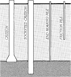
FIGURE 2.37 Deep foundations. Caissons are concrete cylinders poured into drilled holes. They reach through weaker soil (light shading) to bear on competent soil beneath. The end bearing caisson at the left is belled as shown when additional bearing capacity is required. The socketed caisson is drilled into a hard stratum and transfers its load primarily by friction between the soil or rock and the sides of the caisson. Piles are driven into the earth. End bearing piles act in the same way as caissons. The friction pile derives its load-carrying capacity from friction between the soil and the sides of the pile.
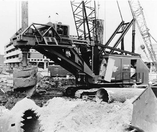
FIGURE 2.38 A 6-foot- (1828-mm)-diameter auger on a telescoping 70-foot (21-m) bar brings up a load of soil from a caisson hole. The auger will be rotated rapidly to spin off the soil before being reinserted in the hole. (Courtesy of Calweld Inc.)
Caissons are large, heavy-duty foundation components. Their shaft diameters range from 18 inches (460 mm) up to 8 feet (2.4 m) or more. Belled caissons are practical only where the bell can be excavated in a cohesive soil (such as clay) that can retain its shape until concrete is poured. Where groundwater is present, the temporary steel casing can prevent flooding of the caisson hole during its construction. But where the bearing stratum is permeable, water may be able to fill the hole from below and caisson construction may not be practical.
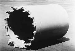
FIGURE 2.39 For cutting through hard material, the caisson drill is equipped with a carbide-toothed coring bucket. (Courtesy of Calweld Inc.)
A socketed caisson (Figure 2.37) is drilled into rock at the bottom rather than belled. Its bearing capacity comes not only from its end bearing, but from the frictional forces between the sides of the caisson and the rock as well. Figure 2.41 shows the installation of a rock caisson or drilled-in caisson, a special type of socketed caisson with a steel H-section core.
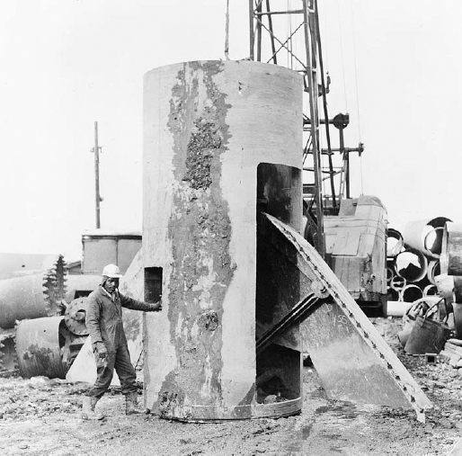
FIGURE 2.40 The bell is formed at the bottom of the caisson shaft by a belling bucket with retractable cutters. The example shown here is for an 8-foot- (2.44-m)-diameter shaft and makes a bell 21 feet (6.40 m) in diameter. (Courtesy of Calweld Inc.)
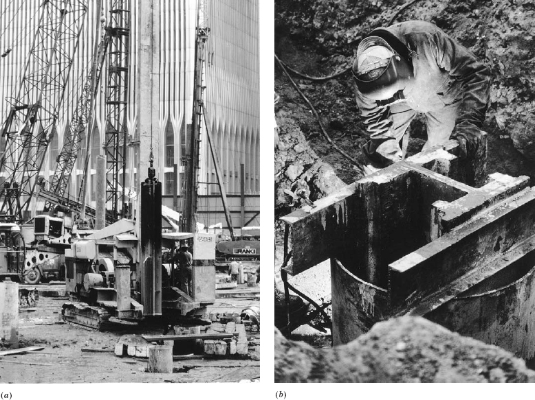
FIGURE 2.41 Installing a rock caisson. (a) The shaft of the caisson has been drilled through softer soil to the rock beneath and cased with a steel pipe. A churn drill is being lowered into the casing to begin advancing the hole into the rock. (b) When the hole has penetrated the required distance into the rock stratum, a heavy steel H-section is lowered into the hole and suspended on steel channels across the mouth of the casing. The space between the casing and the H-section is then filled with concrete, producing a caisson with a very high load-carrying capacity because of the composite structural action of the steel and the concrete. (Courtesy of Franki Foundation Company)
Piles
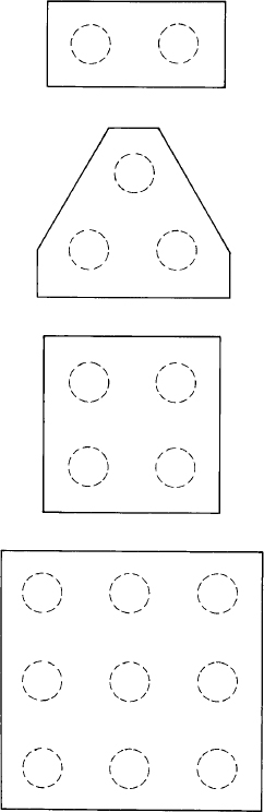
A pile (Figure 2.37) is distinguished from a caisson by being forcibly driven into the earth rather than drilled and poured. It may be used where noncohesive soils, subsurface water conditions, or excessive depth of bearing strata make caissons impractical. The simplest kind of pile is a timber pile, a tree trunk with its branches and bark removed; it is held small end down in a piledriver and beaten into the earth with repeated blows of a heavy mechanical hammer. If a pile is driven until its tip encounters firm resistance from a suitable bearing stratum such as rock, dense sands, or gravels, it is an end bearing pile. If it is driven only into softer material, without encountering a firm bearing layer, it may still develop a considerable load-carrying capacity through frictional resistance between the sides of the pile and the soil through which it is driven; in this case, it is known as a friction pile. (Some piles rely on a combination of end bearing and friction for their strength.) Piles are usually driven closely together in clusters that contain 2 to 25 piles each. The piles in each cluster are later joined at the top by a reinforced concrete pile cap, which distributes the load of the column or wall above among the piles (Figures 2.42 and 2.43).
If . . . solid ground cannot be found, but the place proves to be nothing but a heap of loose earth to the very bottom, or a marsh, then it must be dug up and cleared out and set with piles made of charred alder or olive wood or oak, and these must be driven down by machinery, very closely together. . . .
Marcus Vitruvius Pollio, Roman Architect, The Ten Books on Architecture, 1st century B.C.
FIGURE 2.42 Clusters of two, three, four, and nine piles with their concrete caps, viewed from above. The caps are reinforced to transmit column loads equally into all the piles in the cluster, but the reinforcing steel has been omitted here for the sake of clarity.
End bearing piles work essentially the same as caissons and are used on sites where a firm bearing stratum can be reached by the piles, sometimes at depths of 150 feet (45 m) or more. Each pile is driven “to refusal,” the point at which little additional penetration is made with continuing blows of the hammer, indicating that the pile is firmly embedded in the bearing layer. Friction piles work best in silty, clayey, and sandy soils. They are driven either to a predetermined depth or until a certain level of resistance to hammer blows is encountered, rather than to refusal as with end bearing piles. Clusters of friction piles have the effect of distributing a concentrated load from the structure above into a large volume of soil around and below the cluster, at stresses that lie safely within the capability of the soil (Figure 2.44).
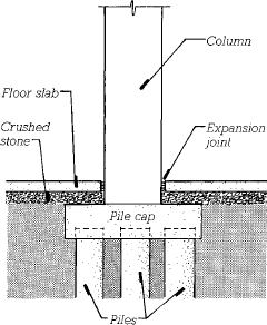
FIGURE 2.43 An elevation view of a pile cap, column, and floor slab.
The loadbearing capacities of piles are calculated in advance based on soil test results and the properties of the piles and piledriver. To verify the correctness of the calculation, test piles are often driven and loaded on the building site before foundation work begins.
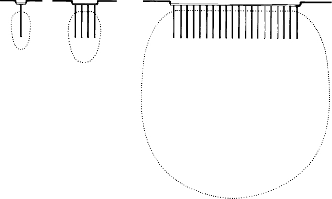
FIGURE 2.44 A single friction pile (left) transmits its load into the earth as an equal shear pressure along the bulb profile indicated by the dotted line. As the size of the pile cluster increases, the piles act together to create a single larger bulb of higher pressure that reaches deeper into the ground. A building with many closely spaced clusters of piles (right) creates a very large, deep bulb. Care must be taken to ensure that large-pressure bulbs do not overstress the soil or cause excessive settlement of the foundation. The settlement of a large group of friction piles in clay, for example, will be considerably greater than that of a single isolated pile.
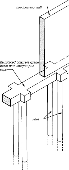
FIGURE 2.45 In order to support a loadbearing wall, pile caps are joined by a grade beam. The reinforcing in the grade beam is similar to that in any ordinary continuous concrete beam and has been omitted for clarity. In some cases, a concrete loadbearing wall can be reinforced to act as its own grade beam.
Where piles are used to support loadbearing walls, reinforced concrete grade beams are constructed between the pile caps to transmit the wall loads to the piles (Figure 2.45). Grade beams are also used with caisson foundations for the same purpose.
Pile Driving
Pile hammers are massive weights lifted by the energy of steam, compressed air, compressed hydraulic fluid, or a diesel explosion, then dropped against a block that is in firm contact with the top of the pile. Single-acting hammers fall by gravity alone, while double-acting hammers are forced downward by reverse application of the energy source that lifts the hammer. The hammer travels on tall vertical rails called leads (pronounced “leeds”) at the front of a piledriver (Figure 2.46). It is first hoisted up the leads to the top of each pile as driving commences, then follows the pile down as it penetrates the earth. The piledriver mechanism includes lifting machinery to raise each pile into position before driving.
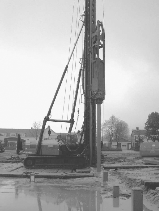
FIGURE 2.46 A piledriver hammers a precast concrete pile into the ground. The pile is supported by the vertical structure (leads) of the piledriver and driven by a heavy piston mechanism that follows it down the leads as it penetrates deeper into the soil. (© David van Mill, Netherlands)
In certain types of soil, piles can be driven more efficiently by vibration than by hammer blows alone, using a vibratory hammer mechanism. Where vibrations from hammering could be a risk to nearby existing structures, some lightweight pile systems can also be installed by rotary drilling or hydraulic pressing.
Pile Materials
Piles may be made of timber, steel, concrete, and various combinations of these materials (Figure 2.47). Timber piles have been used since Roman times, when they were driven by large mechanical hammers hoisted by muscle power. Their main advantage is that they are economical for lightly loaded foundations. On the minus side, they cannot be spliced during driving and are, therefore, limited to the length of available tree trunks, approximately 65 feet (20 m). Unless pressure treated with a wood preservative or completely submerged below the water table, they will decay (the lack of free oxygen in the water prohibits organic growth). Relatively small hammers must be used in driving timber piles to avoid splitting them. Capacities of individual timber piles lie in the range of 10 to 55 tons (9000 to 50,000 kg).
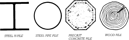
FIGURE 2.47 Cross sections of common types of piles. Precast concrete piles may be square or round instead of the octagonal section shown here and may be hollow in the larger sizes.
Two forms of steel piles are used, H-piles and pipe piles. H-piles are special hot-rolled, wide-flange sections, 8 to 14 inches (200 to 355 mm) deep, which are approximately square in cross section. They are used mostly in end bearing applications. H-piles displace relatively little soil during driving. This minimizes the upward displacement of adjacent soil, called heaving, that sometimes occurs when many piles are driven close together. Heaving can be a particular problem on urban sites, where it can lift adjacent buildings.
H-piles can be brought to the site in any convenient lengths, welded together as driving progresses to form any necessary length of pile, and cut off with an oxyacetylene torch when the required depth is reached. The cutoff ends can then be welded onto other piles to avoid waste. Corrosion can be a problem in some soils, however, and unlike closed pipe piles and hollow precast concrete piles, H-piles cannot be inspected after driving to be sure they are straight and undamaged. Allowable loads on H-piles run from 30 to 225 tons (27,000 to 204,000 kg).
Steel pipe piles have diameters of 8 to 16 inches (200 to 400 mm). They may be driven with the lower end either open or closed with a heavy steel plate. An open pile is easier to drive than a closed one, but its interior must be cleaned of soil and inspected before being filled with concrete, whereas a closed pile can be inspected and concreted immediately after driving. Pipe piles are stiff and can carry loads from 40 to 300 tons (36,000 to 270,000 kg). They displace relatively large amounts of soil during driving, which can lead to upward heaving of nearby soil and buildings. The larger sizes of pipe piles require a very heavy hammer for driving.
Minipiles, also called pin piles or micropiles, are a lightweight form of steel piles made from steel bar or pipe 2 to 12 inches (50 to 300 mm) in diameter. Minipiles are inserted into holes drilled in the soil and grouted in place. When installed within existing buildings, they may also be forced into the soil by hydraulic jacks pushing downward on the pile and upward on the building structure. Since no hammering is required, they are a good choice for repair or improvement of existing foundations where vibrations from the hammering of conventional piles could damage the existing structure or disrupt ongoing activities within the building (Figure 2.54). Where vertical space is limited, such as when working in the basement of an existing building, minipiles can be installed in individual sections as short as 3 feet (1 m) that are threaded end-to-end as driving progresses. Minipiles can reach depths as great as 200 feet (60 m) and have working capacities as great as 200 to 300 tons (180,000 to 270,000 kg).
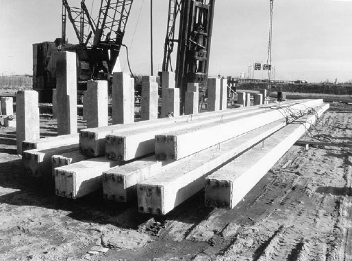
FIGURE 2.48 Precast, prestressed concrete piles. Lifting loops are cast into the sides of the piles as crane attachments for hoisting them into a vertical position. (Courtesy of Lone Star/San-Vel Concrete)
Precast concrete piles are square, octagonal, or round in section, and in large sizes often have open cores to allow inspection (Figures 2.47–2.49). Most are prestressed, but some for smaller buildings are merely reinforced (for an explanation of prestressing, see pages 544–548). Typical cross-sectional dimensions range from 10 to 16 inches (250 to 400 mm) and bearing capacities from 45 to 500 tons (40,000 to 450,000 kg). Advantages of precast piles include high load capacity, an absence of corrosion or decay problems, and, in most situations, a relative economy of cost. Precast piles must be handled carefully to avoid bending and cracking before installation. Splices between lengths of precast piling can be made effectively with mechanical fastening devices that are cast into the ends of the sections.
A sitecast concrete pile is made by driving a hollow steel shell into the ground and filling it with concrete. The shell is sometimes corrugated to increase its stiffness; if the corrugations are circumferential, a heavy steel mandrel (a stiff, tight-fitting liner) is inserted in the shell during driving to protect the shell from collapse, then withdrawn before concreting. Some shells with longitudinal corrugations are stiff enough that they do not require mandrels. Some types of mandrel-driven piles are limited in length, and the larger diameters of sitecast piles (up to 16 inches, or 400 mm) can cause ground heaving. Load capacities range from 45 to 150 tons (40,000 to 136,000 kg). The primary reason to use sitecast concrete piles is their economy.
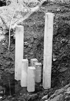
FIGURE 2.49 A driven cluster of six precast concrete piles, ready for cutting off and capping. (Photo by Alvin Ericson)
There is a variety of proprietary sitecast concrete pile systems, each with various advantages and disadvantages (Figure 2.50). Concrete pressure-injected footings (Figure 2.51) share characteristics of piles, piers, and footings. They are highly resistant to uplift forces, a property that is useful for tall, slender buildings in which there is a potential for overturning of the building, and for tensile anchors for tent and pneumatic structures. Rammed aggregate piers and stone columns are similar to pressure-injected footings, but are constructed of crushed rock that has been densely compacted into holes created by drilling or the action of proprietary vibrating probes.
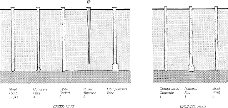
FIGURE 2.50 Some proprietary types of sitecast concrete piles. All are cast into steel casings that have been driven into the ground; the uncased piles are made by withdrawing the casing as the concrete is poured and saving it for subsequent reuse. The numbers refer to the methods of driving that may be used with each: 1. Mandrel driven. 2. Driven from the top of the tube. 3. Driven from the bottom of the tube to avoid buckling it. 4. Jetted. Jetting is accomplished by advancing a high-pressure water nozzle ahead of the pile to wash the soil back alongside the pile to the surface. Jetting has a tendency to disrupt the soil around the pile, so it is not a favored method of driving under most circumstances.
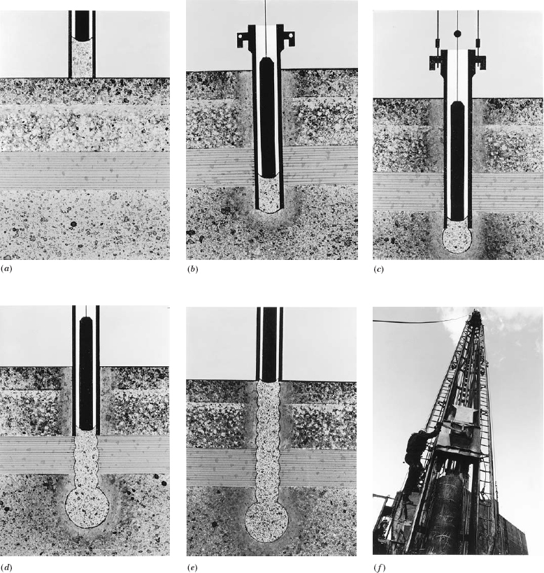
FIGURE 2.51 Steps in the construction of a proprietary pressure-injected, bottom-driven concrete pile footing. (a) A charge of a very low-moisture concrete mix is inserted into the bottom of the steel drive tube at the surface of the ground and compacted into a sealing plug with repeated blows of a drop hammer. (b) As the drop hammer drives the sealing plug into the ground, the drive tube is pulled along by the friction between the plug and the tube. (c) When the desired depth is reached, the tube is held and a bulb of concrete is formed by adding small charges of concrete and driving the concrete out into the soil with the drop hammer. The bulb provides an increased bearing area for the pile and strengthens the bearing stratum by compaction. (d, e) The shaft is formed of additional compacted concrete as the tube is withdrawn. (f) Charges of concrete are dropped into the tube from a special bucket supported on the leads of the driving equipment. (Courtesy of Franki Foundation Company)
Seismic Base Isolation
In areas where strong earthquakes are common, buildings are sometimes placed on base isolators. When significant ground movement occurs, the base isolators flex or yield to absorb a significant portion of this movement; as a result, the building and its substructure move significantly less than they would otherwise, reducing the forces acting on the structure and lessening the potential for damage. A frequently used type of base isolator is a multilayered sandwich of rubber and steel plates (Figure 2.52). The rubber layers deform in shear to allow the rectangular isolator to become a parallelogram in cross section in response to relative motion between the ground and the building. A lead core deforms enough to allow this motion to occur, provides damping action, and keeps the layers of the sandwich aligned.
UNDERPINNING
Underpinning is the process of strengthening and stabilizing the foundations of an existing building. It may be required for any of several reasons: The existing foundations may never have been adequate to carry their loads, leading to excessive settlement of the building over time. A change in building use or additions to the building may overload the existing foundations. New construction near a building may disturb the soil around its foundations or require that its foundations be carried deeper. Whatever the cause, underpinning is a highly specialized task that is seldom the same for any two buildings. Three different alternatives are available when foundation capacity needs to be increased: The foundations may be enlarged; new, deep foundations can be inserted under shallow ones to carry the load to a deeper, stronger stratum of soil; or the soil itself can be strengthened by grouting or by chemical treatment. Figures 2.53 and 2.54 illustrate in diagrammatic form some selected concepts of underpinning.
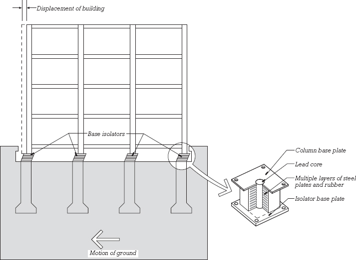
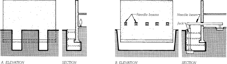
FIGURE 2.53 Two methods of supporting a building while carrying out underpinning work beneath its foundation, each shown in both elevation and section. (a) Trenches are dug beneath the existing foundation at intervals, leaving the majority of the foundation supported by the soil. When portions of the new foundations have been completed in the trenches, using one of the types of underpinning shown in Figure 2.54, another set of trenches is dug between them and the remainder of the foundations is completed. (b) The foundations of an entire wall can be exposed at once by needling, in which the wall is supported temporarily on needle beams threaded through holes cut in the wall. After underpinning has been accomplished, the jacks and needle beams are removed and the trench is backfilled.
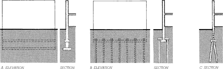
FIGURE 2.54 Three types of underpinning. (a) A new foundation wall and footing are constructed beneath the existing foundation. (b) New piles or caissons are constructed on either side of the existing foundation. (c) Minipiles are inserted through the existing foundation. Minipiles do not generally require excavation or temporary support of the building.
RETAINING WALLS
A retaining wall holds soil back to create an abrupt change in the elevation of the ground. A retaining wall must resist the pressure of the earth that bears against it on the uphill side. Retaining walls may be made of masonry, preservative-treated wood, coated or galvanized steel, precast concrete, or, most commonly, sitecast concrete.
The structural design of a retaining wall must take into account such factors as the height of the wall, the character of the soil behind the wall, the presence or absence of groundwater behind the wall, any structures whose foundations apply pressure to the soil behind the wall, and the character of the soil beneath the base of the wall, which must support the footing that keeps the wall in place. The rate of structural failure in retaining walls is high relative to the rate of failure in other types of structures. Failure may occur through fracture of the wall, overturning of the wall due to soil failure, lateral sliding of the wall, or undermining of the wall by flowing groundwater (Figure 2.55). Careful engineering design and site supervision are crucial to the success of a retaining wall.
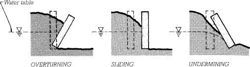
FIGURE 2.55 Three failure mechanisms in retaining walls. The high water table shown in these illustrations creates pressure against the walls that contributes to their failure. The undermining failure is directly attributable to groundwater running beneath the base of the wall, carrying soil with it.
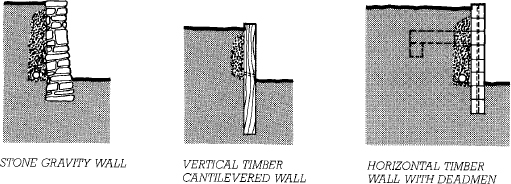
FIGURE 2.56 Three types of simple retaining walls, usually used for heights not exceeding 3 feet (900 mm). The deadmen in the horizontal timber wall are timbers embedded in the soil behind the wall and connected to it with timbers inserted into the wall at right angles. The timbers, which should be pressure treated with a wood preservative, are held together with very large spikes or with steel reinforcing bars driven into drilled holes. The crushed-stone drainage trench behind each wall is important as a means of relieving water pressure against the wall to prevent wall failure. With proper engineering design, any of these types of construction can also be used for taller retaining walls.
There are many ways of building retaining walls. For walls less than 3 feet (900 mm) in height, simple, unreinforced walls of various types are often appropriate (Figure 2.56). For taller walls, and ones subjected to unusual loadings or groundwater, the type most frequently employed today is the cantilevered concrete retaining wall, two examples of which are shown in Figure 2.57. The shape and reinforcing of a cantilevered wall can be custom designed to suit almost any situation. Proprietary systems of interlocking concrete blocks are also used to construct sloping segmental retaining walls that need no steel reinforcing (Figure 2.58).
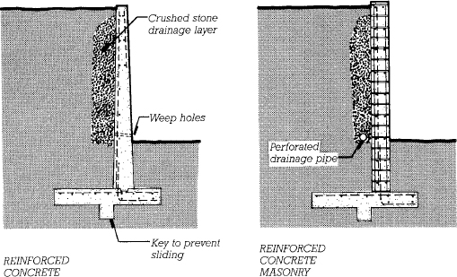
FIGURE 2.57 Cantilevered retaining walls of concrete and concrete masonry. The footing is shaped to resist sliding and overturning, and drainage behind the wall reduces the likelihood of undermining. The pattern of steel reinforcing (broken lines) is designed to resist the tensile forces in the wall.
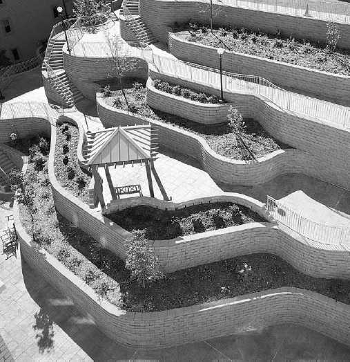
FIGURE 2.58 A segmental retaining wall consisting of specially made concrete blocks designed to interlock and prevent sliding. The wall leans back against the soil it retains; this reduces the amount of soil the wall must retain and makes it more stable against the lateral push of the soil. (Courtesy of VERSA-LOK Retaining Wall Systems)
Earth reinforcing (Figure 2.59) is an economical alternative to conventional retaining walls in many situations. Soil is compacted in thin layers, each containing strips or meshes of galvanized steel, polymer fibers, or glass fibers, which stabilize the soil in much the same manner as the roots of plants. Gabions are another form of earth retention in which corrosion-resistant wire baskets are filled with cobble- or boulder-sized rocks and then stacked to form retaining walls, slope protection, and similar structures.
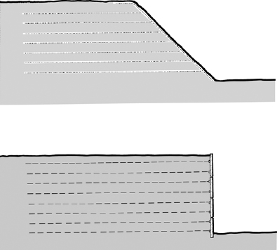
FIGURE 2.59 Two examples of earth reinforcing. The embankment in the top section was placed by alternating thin layers of earth with layers of synthetic mesh fabric. The retaining wall in the lower section is made of precast concrete panels fastened to long galvanized steel straps that run back into the soil.
Geotextiles are flexible fabrics made of chemically inert plastics that are highly resistant to deterioration in the soil. They are used for a variety of purposes relating to site development and the foundations of buildings. As described in the accompanying text, in earth reinforcement or soil reinforcement, a plastic mesh fabric or grid is used to support an earth embankment or retaining wall. The same type of mesh may be utilized in layers to stabilize engineered fill beneath a shallow footing (Figure A), or to stabilize marginal soils under driveways, roads, and airport runways, acting very much as the roots of plants do in preventing the movement of soil particles.
Another geotextile that is introduced later in this chapter is drainage matting, an open matrix of plastic filaments with a feltlike filter fabric laminated onto one side to keep soil particles from entering the matrix. In addition to providing free drainage around foundation walls, drainage matting is often used beneath the soil in the bottoms of planter boxes and under heavy paving tiles on rooftop terraces, where it maintains free passage for the drainage of water above a waterproof membrane.
Synthetic filter fabrics are wrapped over and around subterranean crushed stone drainage layers such as the one frequently used around a foundation drain. In this position, they keep the stone and pipe from gradually becoming clogged with fine soil particles carried by the groundwater. Similar fabrics are used at grade during construction, acting as temporary barriers to filter soil out of water that runs off a construction site, thus preventing contamination of lakes, streams, or stormwater systems.
Special geotextiles are manufactured to stake down on freshly cut slopes to prevent soil erosion and encourage revegetation; some of these are designed to decay and disappear into the soil as plants take over the function of slope stabilization. Another type of geotextile is used for weed control in landscaped beds, where it allows rainwater to penetrate the soil but blocks sunlight, preventing weeds from sprouting.
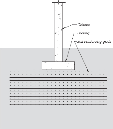
WATERPROOFING AND DRAINAGE
Where building substructures enclose basements, parking garages, or other usable space, groundwater must be kept out. Concrete alone is rarely adequate for this purpose. Moisture can migrate through its microscopic pores, or through other pathways created by shrinkage cracks, form tie holes (form ties, used in sitecast concrete construction, are explained in Chapter 14), utility penetrations, and the joints between concrete pours. To ensure a substructure’s resistance to water entry, two approaches are used: drainage and waterproofing. Drainage draws groundwater away from a foundation, reducing the volume and pressure of water acting on the foundation’s walls and slabs. Waterproofing acts as a barrier, stopping water that reaches the foundation from passing though to the interior.
Drainage, consisting of some combination of drainage backfill (well-sorted crushed stone or gravel), drainage mat, and perforated drain piping, is used with almost every building substructure (Figure 2.60). Drainage mat is a manufactured component that may be made of a loose mat of stiff, inert fibers, a plastic egg-crate structure, or some other very open, porous material. It is faced on the outside with a filter fabric that prevents fine soil particles from entering and clogging the drainage passages in the mat. Any subterranean water that approaches the wall descends through the porous material of the mat to the drain pipe at the footing. Perforated drain piping is frequently laid around the outside perimeter of a building foundation. The pipes are 4 or 6 inches (100 or 150 mm) in diameter and provide an open channel in the crushed stone bed through which water can flow by gravity either “to daylight” at a lower elevation on a sloping site, to a municipal storm sewer system, or to a sump pit that can be automatically pumped dry whenever it fills. The pipes are laid at least 6 inches (150 mm) below the top of the basement floor slab to maintain the groundwater level safely below that of the slab. Perforations in the pipes face downward so that water is drained from the lowest possible level. Where groundwater conditions are severe, rows of perforated pipe may be installed under the basement slab as well (Figure 2.61).
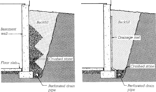
FIGURE 2.60 Two methods of relieving water pressure around a building substructure by drainage. The gravel drain (left) is hard to do well because of the difficulty of depositing the crushed stone and backfill soil in neatly separated, alternating layers. The drainage mat (right) is easier and often more economical to install.
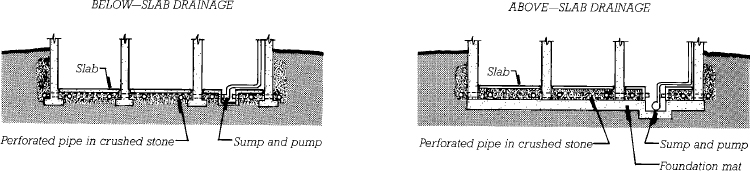
FIGURE 2.61 For a high degree of security against substructure flooding, drainage both around and under the basement is required, as seen here in a section view. Above-slab drainage is used in buildings with mat foundations.
On most foundations, some form of water-repelling barrier is also used to protect against the passage of groundwater. Dampproofing is a moisture-resistant cement plaster or asphalt compound commonly applied to residential basement walls and to other substructures where groundwater conditions are mild or waterproofing requirements are not critical. Cement plaster dampproofing, or parge coating, is light gray in color and troweled on. Asphalt or bituminous dampproofing is dark in color and is applied in liquid form by spray, roller, or trowel. Dampproofing is less expensive and less resistant to water passage than true waterproofing.
Waterproofing, unlike dampproofing, can prevent the passage of water even under conditions of hydrostatic pressure. It is used where groundwater conditions are severe or the need to protect subgrade space from moisture is critical. Waterproof membranes are most commonly formulated from plastics, asphalt compounds, or synthetic rubbers and come in a great variety of forms.
Liquid waterproofing is applied by spray gun, roller, or squeegee and then allowed to cure in place. It is easy to install and easy to form around complex shapes. When fully cured, the finished membrane is seamless and fully bonded to the underlying substrate. However, because liquid membranes are formed in the field, they are subject to uneven application, and the surfaces to which they are applied must be clean, smooth, and dry to ensure reliable adhesion of the membrane.
Preformed sheet membrane waterproofing may be adhered or mechanically fastened to substructure walls or laid loosely over horizontal surfaces (Figure 2.62). Fabricated under controlled factory conditions, sheet membranes are reliably uniform in material quality and thickness. However, they can be more difficult to form around complex shapes, and the seams between sheets, which are sealed in the field, may be subject to lapses in quality. Sheet membranes that are loosely laid or mechanically fastened can be used over substrates that will not bond with liquid-applied or adhered sheet membranes. They are also a good choice where substrate cracking or movement may be expected, because such movement is less likely to stress or damage the membrane. An advantage of adhered membranes (both sheet and liquid) is that in the case of a defect, water cannot travel far under the membrane, limiting the extent of water damage that may occur and simplifying the tracing of leaks.
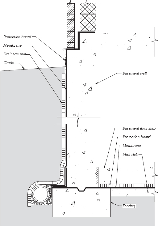
FIGURE 2.62 A diagrammatic representation of the placement of sheet membrane waterproofing around a basement. A mud slab of low-strength concrete was poured to serve as a base for placement of the horizontal membrane. Notice that the vertical and horizontal membranes join to wrap the basement completely in a waterproof enclosure.
Bentonite waterproofing is made from sodium bentonite, a naturally occurring, highly expansive clay. It is most often applied as preformed sheets consisting of dry clay sandwiched within corrugated cardboard, geotextile fabric, or plastic sheets (Figure 2.63). When bentonite comes in contact with moisture, it swells to several times its dry volume and forms an impervious barrier to the further passage of water. Bentonite sheets can be placed directly on the soil under a concrete slab on grade or mechanically attached to uncured, damp concrete walls. In slurry form, bentonite can be sprayed even onto highly irregular, rough stone walls. The swelling behavior of bentonite clay also allows it to adjust to cracking and movement in the substrate.
Integral waterproofing includes cementitious plaster or crystalline admixtures for concrete or mortar that react chemically to stop up the pores of these materials and render them watertight. It may be applied to the surface of existing concrete or masonry or used as an admixture in new concrete. Unlike most other waterproofing materials, many integral waterproofing materials can be applied as negative side waterproofing, that is, applied to the inner side of a concrete wall acting to resist water passage from the opposite side.
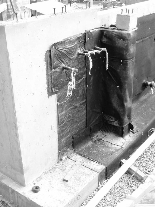
FIGURE 2.63 Waterproofing in progress on a concrete foundation. Leftmost: the bare foundation wall remains exposed. Middle: bentonite waterproofing panels are fastened in place. These panels are lined on the outer face with a black-colored, high-density plastic that adds to the waterproofing qualities of the panel. Right: drainage mat has been installed over the waterproofing. The mat’s outer face of filter fabric is lightly dimpled, telegraphing the egg crate structure of the underlying molded plastic panel. The top edge of the mat is secured in place with an aluminum termination bar that holds the panel in place and keeps dirt and debris from falling behind the panel. Lower right: white perforated drain piping can be seen, temporarily supported on wood blocking and running alongside the footing. (Photo by Joseph Iano)
Blind-side waterproofing is installed prior to the pouring of concrete walls. This occurs most commonly when a substructure wall is built close to a property’s edge, and excavation cannot be enlarged beyond the property line to permit workers access to the outer face of the wall after its construction. Drainage matting is first applied directly to the excavation sheeting, and then any of a number of possible waterproofing membranes are applied over the drainage mat. Later, the concrete wall is poured against the membrane. The sheeting remains permanently in place (Figure 2.64).
Joints in construction require special attention to ensure waterstightness. Preformed waterstops made of plastic, synthetic rubber, or metal can be cast into the mating concrete edges of both moving and nonmoving joints to block the passage of water (Figures 2.65 and 2.66). Waterstops for nonmoving joints such as between concrete pours of a wall or slab can also be made of strips of bentonite or mastic that are temporarily adhered to the edge of one pour. After the adjacent pour is complete, these stops remain embedded in the joint, where they form a watertight barrier (Figure 2.67).
Most waterproofing systems are inaccessible once building construction is complete; they are expected to perform for the life of the building, and even small defects in installation can allow the passage of large volumes of water. For these reasons, waterproofing membranes are inspected carefully during construction and horizontal membranes are often flood tested (submerged for an extended period time while leak-checking is performed) to detect the presence of defects while repairs can still be easily made. Once inspection and testing are complete, membranes are covered with a protection board, insulation board, or drainage matting to shield the membrane from prolonged exposure to sunlight and to prevent physical damage during soil backfilling or subsequent construction operations.
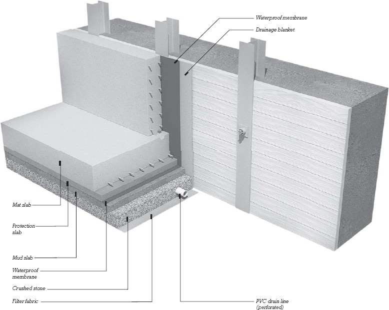
FIGURE 2.64 Blind-side waterproofing is used where there is no working space between a sheeted excavation and the outside of the foundation wall. The drainage mat and waterproof membrane are applied to the sheeting; then the basement wall is poured against them.
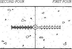
FIGURE 2.65 A synthetic rubber waterstop is used to seal against water penetration at movement joints and at joints between pours of concrete in a foundation. The type shown here is split on one side so that its halves can be placed flat against the formwork where another wall will join the one being poured. After the concrete has been poured and cured and the formwork has been removed from the first wall, the split halves are folded back together before the next wall is poured.
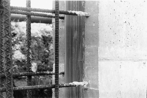
FIGURE 2.66 A rubber waterstop ready for the next pour of a concrete wall, as diagrammed in Figure 2.65. (Courtesy of Vulcan Metal Products, Inc., Birmingham, Alabama)
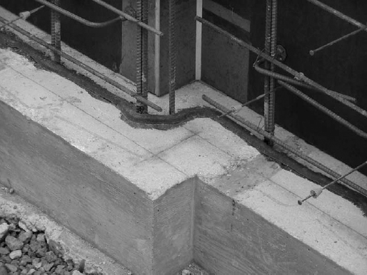
FIGURE 2.67 A bentonite waterstop is adhered to a concrete footing prior to casting of the concrete wall above. Later, if groundwater seepage occurs, the bentonite will swell to fully seal the joint between the two pours. The waterstop is positioned to the side of the steel reinforcing bars closer to the wall’s exterior, also protecting the reinforcing from moisture and corrosion. However, because of bentonite’s expansive force, the waterstop must not be positioned too close to the surface of the wall, or when it swells, it could cause portions of concrete to split away or spall. (Photo by Joseph Iano)
BASEMENT INSULATION
Comfort requirements, heating fuel efficiency, and building codes often require that basement walls be thermally insulated to limit the loss of heat from basements to the soil outside. Thermal insulation may be applied either inside or outside the basement wall. Inside the wall, mineral batt or plastic foam insulation may be installed between wood or steel furring strips, as shown in Figure 23.4. Alternatively, polystyrene foam or glass fiber insulation boards, typically 2 to 4 inches (50 to 100 mm) thick may be placed on the outside of the wall, held by either adhesive, fasteners, or the pressure of the soil. Proprietary products are available that combine insulation board and drainage mat in a single assembly.
SHALLOW FROST-PROTECTED FOUNDATIONS
In shallow frost-protected foundations, extruded polystyrene foam insulation boards can be used in cold climates to construct footings that lie above the normal frost line in the soil, resulting in lower excavation costs. Continuous layers of insulation board are placed around the perimeter of the building in such a way that heat flowing into the soil in winter from the interior of the building maintains the soil beneath the footings at a temperature above freezing (Figure 2.68). Even beneath unheated buildings, properly installed thermal insulation can trap enough geothermal heat around shallow foundations to prevent freezing.
BACKFILLING
After the basement walls have been waterproofed or dampproofed, insulating boards or protection boards have been applied, drainage features have been installed, and internal constructions that support the basement walls, such as interior walls and floors, have been completed, the area around a substructure is backfilled to restore the level of the ground. (A substructure built tightly against sheeted walls of an excavation needs little or no backfilling.) The backfilling operation involves placing soil back against the outside of the basement walls and compacting it there in layers, taking care not to damage drainage or waterproofing components or to exert excessive soil pressure against the walls. An open, fast-draining soil such as gravel or sand is preferred for backfilling because it allows the perimeter drainage system around the basement to do its work. Compaction must be sufficient to minimize subsequent settling of the backfilled area.
In some situations, especially in backfilling utility trenches under roadways and floor slabs, settling can be virtually eliminated by backfilling with controlled low-strength material (CLSM), which is made from portland cement and/or fly ash (a byproduct of coal-burning power plants), sand, and water. CLSM, sometimes called “flowable fill,” is brought in concrete mixer trucks and poured into the excavation, where it compacts and levels itself, then hardens into soil-like material. The strength of CLSM is matched to the situation: For a utility trench, CLSM is formulated so that it is weak enough to be excavated easily by ordinary digging equipment when the pipe needs servicing, yet as strong as a good-quality compacted backfill. CLSM has many other uses in and around foundations. It is often used to pour mud slabs, which are weak concrete slabs used to create a level, dry base in an irregular, often wet excavation. The mud slab serves as a working surface for the reinforcing and pouring of a foundation mat or basement floor slab and is often the surface to which a waterproofing membrane is applied. CLSM is also used to replace pockets of unstable soil that may be encountered beneath a substructure or to create a stable volume of backfill around a basement wall.
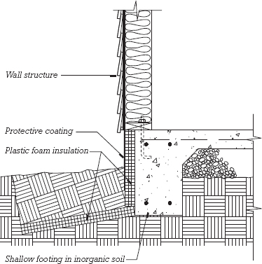
Leave a Reply