Cement factories are to be set up in areas where raw materials, viz., limestone or chalk and shale or clay are abundantly available. It should have adequate transport facilities like road, rail, etc., for easy transport of the finished products. Further, adequate water and power should be available to run the industry without any interruption to production.
Production of cement is performed in three stages, viz.:
- Mixing of raw materials in correct proportion
- Burning of the mixture
- Grinding
There are two processes in the manufacture of cement, viz., the wet process and the dry process, depending upon whether the mixing and grinding of raw materials are done in wet or dry conditions.
A semi-dry process is also in use wherein the raw materials are ground and then mixed with about 10–14% of water and further burnt to chinkering temperature. For many years, the wet process remained popular, which is replaced by the dry process as it consumes less fuel for burning.
6.5.1 Wet Process
Limestone is first crushed to small pieces. Then it is taken to a ball mill or a tube mill and mixed with clay or shale.
Ball mill is in the form of a steel cylinder of about 2 m diameter and length about 2 m. It is positioned in a horizontal position and rotates in a clockwise direction. The inside of the cylinder is fitted with perforated curved plates and steel balls. The material to be ground or mixed is fed from the top. During rotation, the material is ground and mixed by striking against the curved plates and steel balls. The ground and mixed material is collected at the bottom (Fig. 6.2).
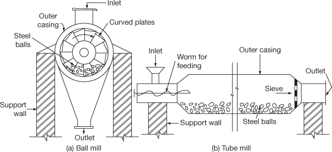
Figure 6.2 Ball and tube mills
The tube mill is in the form of a long horizontal cylinder of 1.5 m diameter and about 8 m long. The cylinder is partly filled with steel balls of varying sizes from 20 to 25 mm diameter. The action of the tube mill is similar to that of a ball mill.
Materials fed into the ball or tube mill are ground with the addition of water to a fine consistency of slurry. The slurry is pumped to slurry tanks or basins where it is kept in an agitated condition. The slurry is checked for the correct composition frequently. The slurry is stored in separate final storage tanks and agitated to keep the slurry in a homogeneous condition.
The correct slurry is sprayed on to the upper end of a rotary kiln. The sprayed slurry passes on the hot surface of a flexible chain (Fig. 6.3). Passing through the kiln of length 30–200 m, the slurry loses moisture and forms flakes. The flakes move from the top to the bottom of the kiln for easy collection of flakes.
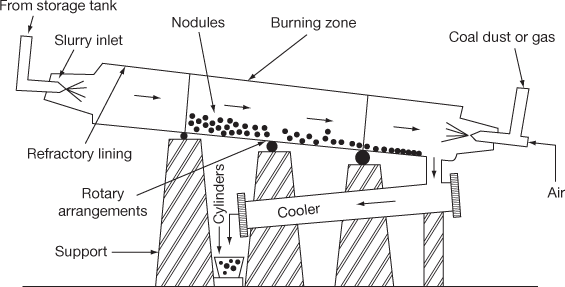
Figure 6.3 Rotary kiln
While passing through the kiln, the slurry undergoes a series of chemical reactions and gets fused and turns into a nodular form of size 3–20 mm known as clinker. The clinker is then cooled and ground in a ball mill with the addition of 3–5% of gypsum. Gypsum is added to prevent quick setting of the cement.
The manufacture of cement by the wet process is shown by a flowchart in Fig. 6.4.
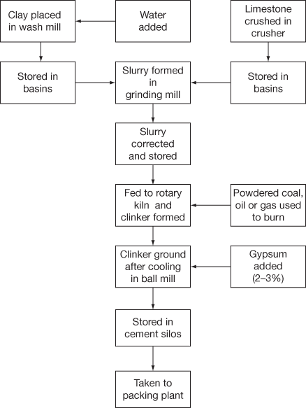
Figure 6.4 Flowchart for wet process
6.5.2 Dry Process
In the dry process, the raw materials are crushed dry, and the correct proportion of the materials is fed into a grinding mill. In the grinding mill, they are dried and finely powdered. The dry powder is then blended and corrected for its right composition and then mixed again by means of compressed air. The aerated powder behaves similar to that of a liquid. The blended mixture is sieved further and passed through a rotating disc called a granulator. In order to make the mixture as pellets, a small amount of water (about 12%) is added.
A small kiln is sufficient for the dry process. This process consumes less quantities of coal and is hence economical.
The pellets are passed through the kiln and form flakes after undergoing a series of chemical reactions and get fused. The fused material turns into nodular form of size 3–20 mm, known as clinker.
Then the clinker is cooled and ground in a ball mill with the addition of 2–3% of gypsum. The stages in the manufacture of cement by the dry process are shown in the flowchart (Fig. 6.5).

Figure 6.5 Flowchart for dry process
Leave a Reply