
Testing of fresh and hardened concrete is important in concrete construction. Tests are conducted on fresh concrete to check the workability of concrete, and on hardened concrete to determine the strength, creep effects, durability, etc.
8.10.1 Testing of Fresh Concrete
The following tests are commonly employed to measure workability of fresh concrete:
- Slump Test
- Compaction factor Test
- Flow Test
- Kelly Ball Test
- Vee Bee Consistometer Test
1. Slump Test
It is the most commonly used method of measuring consistency of concrete. This test can be conducted in the field or in a laboratory. However, this test is not suitable for very wet or very dry concrete.
The apparatus for conducting the slump test consists of a metallic mould in the form of a frustum of a cone with a 20 cm diameter at the bottom, 10 cm diameter at the top and 30 cm in height. A steep tamping rod of 16 mm diameter, 0.6 m long with a bullet end is used for tamping.
The internal surface of the mould is thoroughly cleaned and placed on a smooth non-absorbent horizontal surface. The mould is filled in four layers of equal height. Each layer is compacted by giving 25 blows with the tamping rod uniformly. After filling the mould and rodded, the excess concrete is shaken off and levelled.
The mould is lifted upwards from the concrete immediately by raising it slowly. This allows the concrete to subside. This subsidence is referred to as the slump of concrete. The difference in height of the mould and that of the subsided concrete is measured and reported in mm, which is considered to be the slump up of concrete.
The pattern of slump also represents the characteristics of concrete (Fig. 8.2). If the slump of the concrete is even, it is called a true slump. If one-half of the cone slides down, it is called a shear slump. In this case the average value of the slump is considered. The shear slump also indicates that the concrete is not cohesive and reflects segregation. Concrete mixes are classified based on the slump as given in Table 8.12.
Table 8.12 Slump and nature of concrete


Figure 8.2 Types of slumps
Slumps recommended for various works of concrete construction are presented in Table 8.13.
Table 8.13 Recommended slump for concrete works

The slump test can be conducted both in the laboratory and at the work site. The slump test results grant the facility to easily detect the difference in water content of successive batches of the identical mix.
2. Compacting Factor Test
This is a more refined test than the slump test. The test measures the degree of compaction obtained by using certain energy in overcoming the internal friction of the concrete. This property is a measure of workability.
The test apparatus consists of two conical hoppers with bottom doors and a separate cylinder kept at the bottom. The concrete is filled in the top hopper fully without compaction and released successively through the two hoppers and into the bottom cylinder (Fig. 8.3). After striking off the level in the cylinder the weight of the concrete (W1) in the cylinder is determined. The same cylinder is filled with the same batch of concrete and compacted to get the maximum weight (W2). The ratio of the observed weight, W1, to the theoretical weight, W2, i.e., W1/W2 is the compacting factor. The workability, compacting factor and the corresponding slump are given in Table 8.14.

Figure 8.3 Compacting factor test apparatus (dimensions shown are in mm)
Table 8.14 Workability and compacting factor

The compacting factor test measures the quality of concrete, which relates very close to the workability. This test clearly depicts the workability of concrete.
3. Flow Test
This test gives an indication of the quality of concrete with respect to consistency, cohesiveness and non-segregation. In this test a mass of concrete is subjected to floating, and the flow or spread of the concrete is measured. The flow is related to workability.
The test apparatus consists of a flow table of 76 mm diameter on which concentric circles are marked (Fig. 8.4). A mould similar to that used in the Slump Test with a base diameter of 25 cm, an upper diameter of 17 cm and a height of 12 cm is used. The mould is kept on a clean table, and concrete is filled in two layers with each layer being rodded 25 times with a tamping rod of 1.6 cm diameter and 61 cm long with a rounded end. The excess concrete at the top of the mould is levelled. The mould is lifted vertically upwards completely. The concrete stands on its own without support.
The table is raised and dropped 12.5 mm with the cam arrangement, 15 times in about 15 seconds. The diameter of the spread concrete is measured in 6 directions and the average value is taken. The flow of the concrete is defined as the percentage increase in the average diameter of the spread concrete to the base diameter of the spread concrete to the base diameter of the mould, i.e.,

The value varies from 0 to 150%.
The spread pattern of the concrete also reflects the tendency of the segregation. The flow test is a laboratory test.

Figure 8.4 Flow table apparatus
4. Kelly Ball Test
It consists of a metal hemisphere of 15 cm diameter weighting 13.6 kg (Fig. 8.5). The concrete base should be 20 cm depth, and the minimum distance from the centre of the ball to the nearest edge of the concrete is 23 cm. The ball is gradually lowered to the surface of the concrete. The depth of the penetration is read immediately on the stem to the nearest 6 mm. The test can be done in a shorter periods of about 15 seconds. This test gives more consistent results than slump tests.
The test can be performed in the field and it can be performed on the concrete placed on the site.

Figure 8.5 Kelly ball
5. Vee Bee Consistometer Test
This test consists of a vibrating table, a metal pot, a sheet metal cone and a standard iron rod (Fig. 8.6). A slump cone with concrete is placed inside the sheet metal cylindrical pot of the consistometer. The glass disc is turned and placed on the top of the concrete in the pot. The vibrator is switched on, and the stop watch is started simultaneously. The vibrator is kept on till the concrete in the cone assumes a cylindrical shape. The time is noted. The time required in seconds for the concrete to change from the shape of a cone to the shape of a cylinder is known as the Vee Bee Degree.
This is a good laboratory method and is more suitable for very dry concrete. This test measures the workability indirectly.

Figure 8.6 Vee Bee consistometer-type VBR
8.10.2 Testing of Hardened Concrete
The following tests are conducted for hardened concrete:
- Compressive Strength Test
- Flexural Strength Test
- Split-tension test
1. Compressive Strength Test
This is an important test as most of the properties of concrete are qualitatively related to it. It is an easy and most common test. The tests are conducted on cubical or cylindrical specimens.
The cube specimen is of size 15 cm × 15 cm × 15 cm, and the cylinder is of 15 cm diameter and is 30 cm long. The largest nominal size of the aggregate does not exceed 20 mm. The moulds must be of metal moulds, preferably of steel or cast iron. The moulds are made in such a way that the specimens are taken out without damage. A tamping steel bar of 16 mm diameter and 0.6 m long with a bullet end is used for compacting.
The test cube specimens are made as soon as practicable. The concrete is filled into the mould up to approximately 5 cm. Each layer is compacted by the tamping rod (25–35 strokes depending on 10–15 cm depth) or by vibration. The top layer is compacted using a trowel. It is covered with a glass or metal plate to prevent evaporation. The specimens are demoulded after 24 hours and submerged in fresh clean water or saturated lime solution and kept there and taken out just prior to the test. The water should be maintained approximately at 27º ± 2 ºC and on no account must the specimens be allowed to dry out.
The specimens are tested in a compression testing machine on completion of 7 and 28 days. Compression on the cube or cylinder undergoes lateral expansion owing to Poisson’s ratio effect.
Cylindrical specimens are less affected by end restraints caused by plaster, and hence it is believed to give more uniform results than the cube. Further, the cylinder simulates the real condition in the field in respect of the direction of the load. Normally, the strength of the cylindrical specimen is taken as 0.8 times the strength of cubical specimens.
2. Flexural Strength Test
Concrete is relatively strong in compression and weak in tension. Tensile stresses can develop in concrete due to drying, shrinkage, rusting of steel reinforcement, temperature gradient and many other reasons. Hence, the tensile strength of concrete gains importance.
Direct measurement of tensile strength is not feasible. Hence, beam tests are found to be dependable to measure the flexural strength property of concrete. The Modulus of Rupture is taken to be the extreme fibre stress in bending.
The value of the Modulus of Rupture depends on the dimension of the beam and the type of loading. The loading adopted is central or two-third point loading. In the central point loading, the maximum fibre stress occurs below the point of loading where the bending moment is at the maximum. In the two-point loading, a critical crack may appear at any section, where the bending moment is at the maximum, or the resistance is weak. In general, the two-point loading yields a lower value of the Modulus of Rupture than the centre point loading.
The various types of loading are shown in Fig. 8.7. The size of the specimen is 15 cm × 15 cm × 70 cm. In case of concrete with an aggregate of size less than 20 mm, a beam size of 10 cm × 10 cm × 50 cm may be used. The mould may be of metal or steel or cast iron. The tamping bar may be of steel weighing 2 kg, 40 cm long and should have a ramming face of 25 mm2.
The testing machine should have sufficient loading capacity with a specific rate of loading such that the permissible errors on the applied load should not be greater than ± 0.50%.
The flexural strength of the specimen is expressed as the Modulus of Rupture, fb, as
![]() (8.3)
(8.3)
where P = maximum load in kg applied to the specimen
a = 17–20 cm for a 15.0-cm specimen or >13.3 cm for a 10.0-cm specimen
b = measured width in cm of the specimen
d = measured depth in cm of the specimen at the point of failure
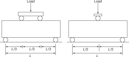
Figure 8.7 Loading arrangement in the flexural beam test
If a is less than 17.0 cm for a 15.0-cm specimen or less than 11.0 cm for a 10.0 -cm specimen, the results of the test may be discarded.
3. Split-tension Test
This is an indirect tension test. This is also referred to as the Brazilian test. In this test a cylindrical specimen is placed horizontally between the loading surfaces of a compression testing machine. The load is applied until failure of the cylinder along the vertical diameter. The test specimen is shown in Fig. 8.8.
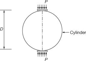
Figure 8.8 Split-tension test
When the load is applied along the diameter, compressive stresses develop immediately below the two generators to which the load is applied. But a larger portion about 5/6th of the depth is subjected to tensile stress.
The main advantage of the test is that the same compression testing machine and the same cylindrical specimen used for the compression test may be used. Narrow packing strips of suitable material such as plywood are used to reduce the high compressive stresses.
The Split-tension Test is simple to perform and generally gives more uniform results. The tensile strength from the Split-tension Test is almost near its true tensile strength than the Modulus of Rupture. The Split-tension Test gives 5–12% higher value than the direct tensile strength.
Leave a Reply