
MASONRY VENEER CURTAIN WALLS
shows in a series of steps how a brick masonry veneer (a single wythe of brick masonry separated by a cavity from a structural backup wall) may be applied to a reinforced concrete frame. The veneer may also be made of stone. The veneer wythe is erected brick by brick or stone by stone with conventional mortar, starting from a steel shelf angle that is attached to the structural frame at each floor (Figure 20.2). The construction process and details are essentially the same as for a masonry cavity wall of a single-story building, but there are some crucial differences: To prevent normal movements in the frame of the building from stressing the masonry veneer, and to allow the veneer to expand and contract without distress, there must be a soft joint (horizontal expansion joint) beneath each shelf angle (Figure 20.3). This joint must be dimensioned to absorb the maximum anticipated sum of column creep, brick expansion, spandrel beam deflection, and a dimensional tolerance to allow for construction inaccuracies while not exceeding the maximum safe compressibility of the sealant. Masonry curtain walls also must be divided vertically by movement joints (vertical expansion joints) to allow the frame and the masonry cladding to expand and contract independently of one another (Figure 20.4).
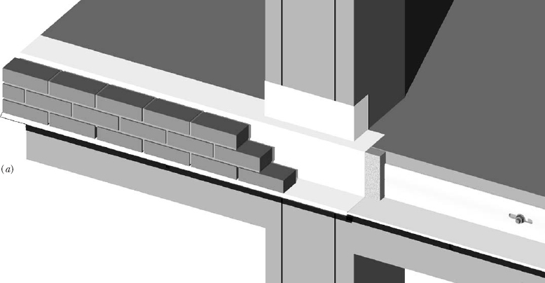
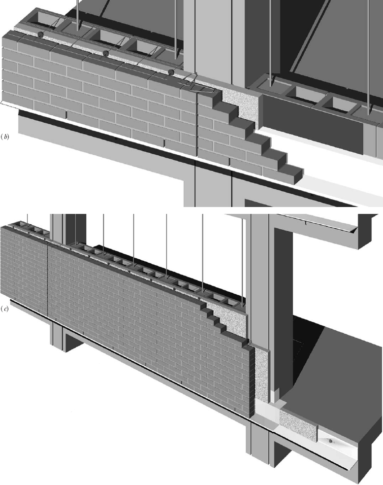
FIGURE 20.1 Construction sequence for a brick veneer curtain wall supported by a reinforced concrete frame. (a) Before the concrete frame of the building was cast, inserts were put into the formwork to form attachments for the brick veneer, including wedge anchors along the line of each shelf angle, two vertical dovetail slots in each column, short vertical dovetail slots in the spandrel beams, and horizontal reglets in the centers of the spandrel beams to accept the inner edge of a flashing over each window head (see pages 624 and 625 for pictures of these inserts). To begin installation of the brick veneer, a steel shelf angle is bolted to each spandrel beam, using malleable iron wedge inserts as shown in Figure 20.2. A slab of polystyrene foam thermal insulation (gray) is placed over the upright leg of the shelf angle, and a continuous flashing (white) is installed over the shelf angle, the foam, and the edge of the floor slab. This flashing also wraps around the front of the column. All the seams in the flashing are overlapped and made watertight with sealant. The first course of brickwork is laid directly on the shelf angle and flashing, without a bed joint of mortar. Every third head joint is left open in this first course to form a weep hole. Three courses of brickwork bring the veneer up to the level of the floor slab. (b) The first course of the concrete masonry backup wall is laid. Vertical reinforcing bars are grouted into the hollow cores of the backup wall at intervals specified by the structural engineer. An asphaltic coating is applied to the backup wall to act as an air and moisture barrier. Three more courses of brick veneer bring the top of the veneer up to the level of the top of the first course of concrete masonry. Polystyrene foam thermal insulation is placed against the concrete masonry. A combination joint reinforcing and masonry tie made of heavy steel wires is laid on top of the masonry, tying the brick veneer to the backup wall. Plastic clips are snapped onto the tie rods of the joint reinforcing to hold the insulation in position. A vertical expansion joint in the brick veneer is provided at the centerline of each column. A heavy wire masonry tie in a dovetail slot anchors the brick veneer to the column on each side of the joint; another such anchor is lying loose on top of the bricks, ready to be installed, in this view. (c) The wall rises in vertical increments of 16 inches (400 mm), which equals six brick courses or two concrete masonry courses. This is also the vertical distance between ties and the height of a polystyrene foam insulating panel. A-blocks (see Figure 9.23) are utilized as needed in the backup wall to avoid having to thread blocks over the tops of the vertical reinforcing bars. The vertical expansion joint is sealed with backer rod and sealant. As an alternative to the sequence of operations illustrated here, the backup wall and air barrier may be installed to their full height first, followed later by the installation of insulation and veneer.
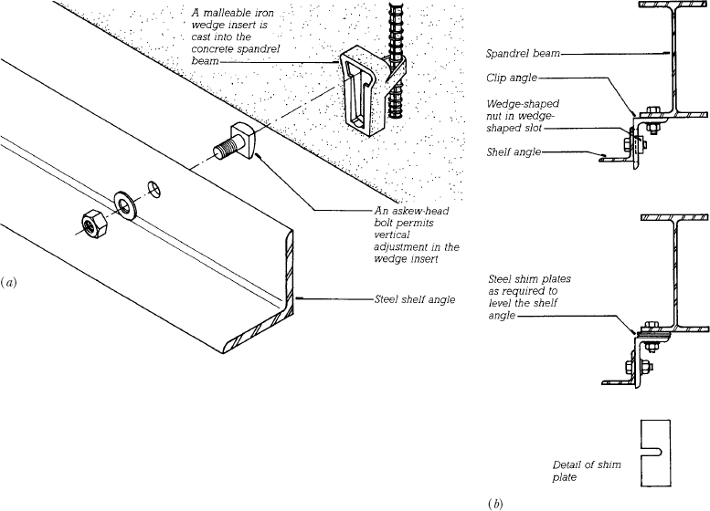
FIGURE 20.2 (a) An example of a cast-in-place anchoring system for attaching a steel shelf angle to a concrete spandrel beam. Steel shims are added as necessary between the shelf angle and the spandrel beam to place the angle exactly in the plane of the facing wythe. (b) The traditional method for attaching shelf angles to steel spandrel beams uses steel clip angles with shim plates as needed to make up for dimensional inaccuracies in the components. In practice, providing anchoring systems with adequate adjustability to account for deviations in the structural frame is often a difficult challenge.
A backup wall of light gauge steel studs covered with water-resistant sheathing panels of gypsum or cementitious materials is often considered to be interchangeable with a concrete masonry backup wall for a masonry facing. The stud wall even has certain advantages over masonry in its lighter weight, its greater ability to contain thermal insulation and electrical wiring, and its greater receptivity to a variety of interior finish materials. However, the steel studs and their fastenings are inherently more flexible than a concrete masonry wall and may deflect enough under maximum wind pressures to cause cracking of brittle masonry veneers. Such cracking often leads to water leakage. Furthermore, if there is leakage through the facing layer of the wall because of cracking, porous masonry, or poor workmanship, the steel studs and fasteners are susceptible to corrosion, and the gypsum sheathing panels are subject to water deterioration.
FIGURE 20.3 A complete detail section of the brick veneer wall that was begun in Figure 20.1 shows how the top of the backup wall is fastened to the underside of the spandrel beam with a series of steel restraint clips that brace the top of the wall against wind loads but allow the spandrel beam to deflect under load. Two lines of backer rod and sealant along the columns and across the top of the backup wall make the backup wall airtight. A soft joint of sealant beneath the shelf angle permits the spandrel beam to deflect without applying force to the brick veneer. The brick ties nearest the underside of the shelf angle are anchored to dovetail slots in the spandrel beam. An additional plastic clip on each wire tie in the center of the cavity acts as a drip to prevent water from clinging to the tie and running toward the backup wall. The interior of the building is finished with gypsum veneer plaster mounted on steel furring channels, similar to the assembly shown in Figure 23.5. (Drawing from Allen, Edward, Architectural Detailing: Function, Constructibility, Aesthetics, New York, John Wiley & Sons, Inc., 1993, reproduced by permission of the publisher)
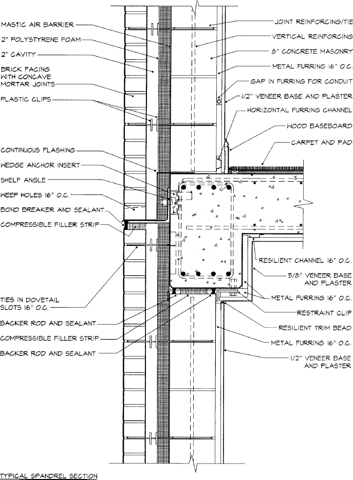
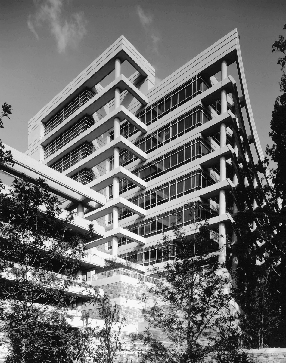
FIGURE 20.4 (a) A carefully detailed brick curtain wall by architects Kallman, McKinnell and Wood covers the steel frame of Hauser Hall at Harvard University. Notice the vertical expansion joint near the far-right corner. (b) At the base of Hauser Hall, the facing wythe is made of limestone blocks. The backup wall consists of steel studs and gypsum sheathing panels. A vertical expansion is visible in the far-left corner in this view. (Photos © Steve Rosenthal)
A concrete masonry backup wall is usually stiffer than the veneer that it supports, so the veneer is unlikely to crack under wind loadings. A concrete masonry backup wall can also, if necessary, maintain its structural integrity despite prolonged periods of wetting. For these reasons, a concrete masonry backup wall is generally preferable to a wall of steel studs. If a steel stud backup system is selected, the studs, masonry ties, and fasteners should be sized very conservatively so as to be stiff enough against wind loadings that the veneer material will not crack. The sheathing material and fasteners should be selected for their durability under damp conditions. Each metal tie that connects the masonry veneer to the studs should be attached directly to a stud with at least two corrosion-resistant screws. The wall must be detailed carefully to keep leaked water away from the backup components. Constant inspection is required during construction to be certain that all these details are faithfully executed and the cavity is kept clean so that it will drain freely.
The structural frame of a building is never absolutely flat or plumb. Thus, the attachment system for the shelf angles must allow for adjustments so that the masonry veneer may be constructed in a precisely vertical plane with level courses. Figure 20.2 shows how this is usually done for both concrete and steel frames. The attachment system in Figure 20.5, which is designed to suspend a masonry veneer spandrel wall over a continuous band of windows, also provides for free adjustment of the shelf angle location.
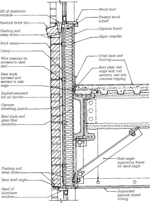
FIGURE 20.5 A detail section of a brick curtain wall that is supported below the level of the spandrel beam on a frame made of steel angles. The supporting frame becomes necessary when continuous horizontal bands of windows are to be installed between brick spandrels. All the connections in the supporting frame are made with bolts in slotted holes to allow for exact alignment of the shelf angle. After the frame has been aligned and before the masonry work begins, the connections are welded to prevent slippage. Shelf angle constructions for masonry curtain walls require careful engineering to accommodate expected loads and structural deflections.
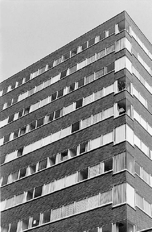
FIGURE 20.6 The detail shown in Figure 20.5 allows the construction of brick spandrels between continuous horizontal bands of glass. (Photo by Edward Allen)
The flashing above the shelf angle should project beyond the face of the masonry by 1 inch (25 mm) or so and should be bent downward at a 45–degree angle to form a drip. In this way, it is able to conduct water that has leaked into the cavity back to the outdoors and to drain it safely away from the wall. If a flexible plastic or composite flashing is used, it should be cemented to a strip of sheet metal flashing over the shelf angle, with the sheet metal forming the projecting drip.
Many architects, because they wish to maintain the fiction that a masonry veneer is actually a solid masonry wall, find the soft joint and projecting flashing objectionable. They use specially molded bricks with a face lip that hangs down over the shelf angle to conceal it from view, and they do not allow the flashing to project out of the wall. The color of the sealant that they use in the soft joint is matched as closely as possible to the color of the mortar. Unfortunately, the use of lipped bricks and recessed flashings is very risky. The recessed flashing allows water to accumulate around the toe of the angle, causing the angle to rust. Freeze-thaw action and the expansion of the steel as it rusts are likely to cause the lips to spall off of the bricks. Eventually, the deterioration along the line of the shelf angle becomes unsightly. Worse yet, the stability of the veneer may be endangered by failure of the corroded shelf angle. A better strategy for the conscientious architect is to find a way to express visually the presence of the shelf angle, flashing, and soft joint, and to make them positive features of the building facade. A soldier course or cut stone sill above each shelf angle is a good start toward a frank expression of a constructional necessity.
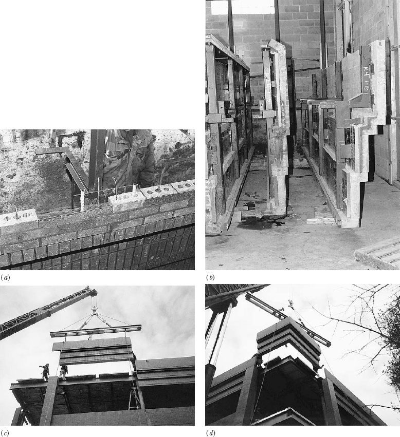
FIGURE 20.7 Fabrication and installation of a brick panel curtain wall. (a) Masons construct the panels in a factory, using conventional bricks and mortar. Both horizontal and vertical reinforcing are used, the vertical bars being grouted into the hollow cores of the bricks. (b) Brick panels are stored to await shipment, complete with thermal insulation. The welded metal brackets are for attachment to the building; the structural strength of the panel comes primarily from the reinforced masonry, not the brackets. (c) A crane lifts a parapet panel to its final position. (d) Corners can be constructed as single panels. (Panelized masonry by Vet-O-Vitz Masonry Systems, Inc., Brunswick, Ohio)
Prefabricated Brick Panel Curtain Walls
Figure 20.7 shows the use of prefabricated reinforced brick panels for cladding. Masons construct the panels while working comfortably at ground level in a factory. Horizontal reinforcing may be laid into the mortar joints or grouted into channel-shaped bricks. Vertical reinforcing bars are placed in grouted cavities of hollow-core bricks. These panels are self-rigid; they need no structural backup and can be fastened to the building in much the same way as precast concrete panels. A steel stud backup wall is required to carry thermal insulation, electrical wiring, and an interior finish layer, but it has no structural role.
Leave a Reply