
A low-slope roof (often referred to, inaccurately, as a “flat” roof) is usually defined as one whose slope is less than 2:12, or 17 percent. A low-slope roof is a highly interactive assembly made up of multiple components. The roof deck is the structural surface that supports the roof. Thermal insulation is installed to slow the passage of heat into and out of the building. An air barrier restricts the leakage of air through the roof assembly, and a vapor retarder is essential in colder climates or when enclosing humid spaces to prevent moisture vapor from condensing within it. The roof membrane is the impervious sheet of material that keeps water out of the building. Drainage components, such as roof drains, gutters, and downspouts, remove the water that runs off the membrane. Around the membrane’s edges and wherever it is penetrated by pipes, vents, expansion joints, electrical conduits, or roof hatches, special flashings and details must be designed and installed to prevent water penetration.
Roof Decks
Previous chapters of this book have presented the types of structural decks ordinarily used under low-slope roofs: wood panels over wood joists, solid wood decking over heavy timber framing, corrugated steel decking, panels of wood fiber bonded together with portland cement, sitecast concrete slab, and precast concrete slab. For a durable low-slope roof installation, it is important that the deck be adequately stiff under expected roof loadings and fully resistant to wind uplift forces. The deck must slope toward drainage points at an inclination sufficient to drain reliably despite the effects of structural deflections. A slope of at least ¼ inch per foot of run (1 in 50, or 2 percent) is normally required by the building code and by most manufacturers of low-slope roof membranes. To create the slopes in a low-slope roof, the beams that support the deck may be sloped by varying the height of the supporting columns. Or the deck may be constructed level and the slopes created by a layer of thermal insulation of varying thickness installed on the top of the deck. This layer may consist of lightweight insulating concrete or a system of tapered rigid insulation boards.
If the slope of a low-slope roof is too shallow, ponding occurs: the formation of puddles of water that stand for extended periods of time, leading to premature deterioration of the roofing materials in those areas. If water accumulates in low spots caused by structural deflections, progressive structural collapse becomes a possibility, with deepening puddles attracting more and more water during rainstorms and becoming heavier and heavier, until the beams or joists become loaded to the point of failure (Figure 16.3).
The roof membrane must be laid over a smooth surface. A wood deck that is to receive a roof membrane should have no large gaps, knotholes, or protruding fasteners. A sitecast concrete deck should be troweled smooth, and a precast concrete plank deck, if not topped with a concrete fill, must be grouted at junctions between planks to fill the cracks and form a smooth surface. A corrugated steel deck must be covered with substrate board, thin panels of rigid insulation, wood, or gypsum board that can bridge the flutes in the deck and create a continuous, smooth surface.
It is extremely important that the deck be dry at the time roofing operations commence to avoid later problems with water vapor trapped under the roof membrane. A deck should not be roofed when rain, snow, or frost is present in or on the deck material. Concrete decks and insulating fills must be fully cured and thoroughly air dried.
If a deck is large in extent, the roofing system should be provided with enough movement joints so that expansion and contraction or other movement within the deck does not excessively stress the overlying membrane. Where building separation joints occur within a building structure, these joints must carry through the roof membrane system as well (Figure 16.27). Where such joints do not occur or are too far apart to satisfy the separation requirements of the membrane, area dividers, which are much like building separation joints but do not extend below the surface of the roof deck, may be installed (Figure 16.28).
Thermal Insulation and Vapor Retarder
Thermal insulation for a low-slope roof may be installed in any of three positions: below the structural deck, between the deck and the membrane, or above the membrane (Figure 16.4).
Insulation Below the Deck
Below the deck, batt insulation of mineral fiber or glass fiber is installed either between framing members or on top of a suspended ceiling assembly. The building code normally requires a ventilated airspace between the insulation and the underside of the deck to dissipate excess water vapor. Below-deck insulation is relatively economical and trouble-free, but it leaves the deck and the membrane exposed to the full range of outdoor temperature fluctuations. In cold climates or when enclosing humid spaces, a vapor retarder is recommended on the warm, conditioned side of the roof insulation to control the diffusion of water vapor into the insulated portions of the roof where condensation could occur.
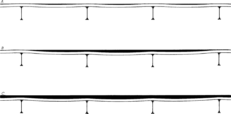
FIGURE 16.3 A low-slope roof with insufficient slope toward a drain is subject to ponding, and possible structural failure through progressive collapse, as demonstrated in this sequence of cross sections. (a) Water stands on the roof in puddles, its weight causing slight deflections of the roof deck between supporting beams or joists. (b) If heavy rainfall continues, the puddles grow and join, and the accumulating weight of the water begins to cause substantial deflections in the supporting structural elements. The deflections encourage water from a broader area of the roof to run into the puddle. (c) As structural deflections increase, the depth of the puddle increases more and more rapidly until the overloaded structure collapses.
Spray foam insulation can also be installed below a roof deck. When air-impermeable foam insulation is used, the risk of moisture accumulation within the assembly is reduced, and ventilation between the deck and the insulation may not be required.
Insulation Between the Deck and the Membrane
The traditional position for low-slope roof insulation is between the deck and the roof membrane. Insulation in this position must be in the form of low-density rigid boards or lightweight concrete in order to support the membrane. The insulation protects the deck from temperature extremes and is itself protected from the weather by the membrane. But the roof membrane in this type of installation remains exposed to extreme temperature variations. Additionally, any moisture that may accumulate in the insulation is trapped beneath the membrane, which can lead to decay of the insulation and roof deck, as well as blistering and eventual rupture of the membrane from vapor pressure. (See the discussion on pages 658–661 for a more in-depth explanation of insulation and vapor retarders.)
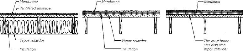
FIGURE 16.4 Low-slope roofs with thermal insulation in three different positions, shown here with a wood joist roof deck. At the left, insulation is located below the deck, with a vapor retarder on the warm side of the insulation. In the center, insulation is placed between the deck and the membrane, with a vapor retarder on the warm side of the insulation. At the right, a protected membrane roof, insulation is placed above the membrane and no separate vapor retarder is required. When insulation is installed below the roof deck, a space that is continuously ventilated with outside air is usually required between the insulation and the deck to prevent water vapor accumulation.
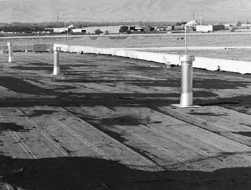
FIGURE 16.5 Topside roof vents are being installed in this built-up roof membrane to release vapor pressure that may accumulate beneath it. (Courtesy of Manville Corporation)
When installing insulation between the deck and the membrane in cold climates, two precautions may be taken: a vapor retarder installed below the insulation and ventilation within the insulation to allow the escape of any moisture that reaches there. Ventilation is accomplished through the installation of topside vents, one per 1000 square feet (100 m2), that allow water vapor to escape upward through the membrane (Figures 16.5 and 16.6). Topside vents are most effective with a loose-laid membrane (a membrane that is not adhered to the underlying surface), which allows trapped moisture to easily work its way toward the vents from any part of the insulating layer.
Insulation Above the Membrane: The Protected Membrane Roof
In a protected membrane roof (PMR) system, insulation is installed above the roof membrane. This offers two advantages: The membrane is protected from extremes of heat and cold, and the membrane is on the warm side of the insulation, where it is immune to vapor blistering problems. Because the insulation itself is exposed to water when placed above the membrane, it must be made of a material that retains its insulating value when wet and does not decay or disintegrate. Extruded polystyrene foam is the one material that has these qualities (Figure 16.7). The panels of polystyrene are either embedded in a coat of hot asphalt to adhere them to the membrane below or are laid loose. They are held down and protected from sunlight (which disintegrates polystyrene) by a layer of ballast, which may consist of crushed stone or gravel, a thin concrete layer laminated at the factory to the upper surface of the insulating board, or interlocking concrete blocks (Figures 16.8, 16.9, and 16.23). Because the membrane in a PMR system is shielded from sunlight and temperature extremes by the insulation and ballast above, it can be expected to last roughly twice as long as in an assembly where it remains directly exposed to these elements. However PMR systems do have potential disadvantages. When the roof insulation is exposed to precipitation, it may absorb moisture and lose some of its resistance to the flow of heat. When performing energy calculation for PMR systems, R-values for roof insulation may be slightly reduced from their standard values to account for such losses. PMR systems may not be appropriate for climates with extended periods of rainy, cold weather, as cool water continuously flowing around and under the insulation boards may negate much of their insulating value. And repairs to protected membrane roofs, if required, are more costly and time-consuming because accessing the roof membrane requires removal of the layers of material above it.
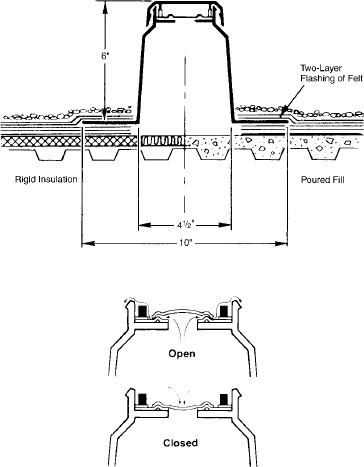
FIGURE 16.6 This proprietary topside roof vent, made of molded plastic with a synthetic rubber valve, allows moisture vapor to escape from beneath the membrane but closes to prevent water or air from entering. (Courtesy of Manville Corporation)
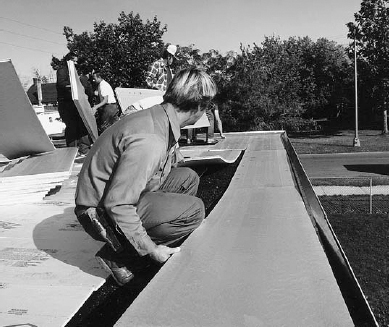
FIGURE 16.7 Installing extruded polystyrene foam insulation over a roof membrane to create a protected membrane roof. (Photograph provided by the Dow Chemical Company)
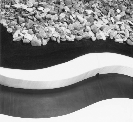
FIGURE 16.8 A cutaway detail of a proprietary type of protected membrane roof shows, from bottom to top, the roof deck, the membrane, polystyrene foam insulation, a polymeric fabric that separates the ballast from the insulation, and the ballast. (Photograph provided by The Dow Chemical Company)
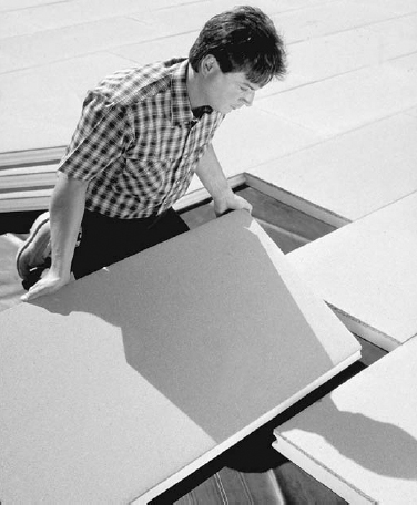
FIGURE 16.9 This proprietary system of 2-inch (50-mm)-thick polystyrene foam insulation for a protected membrane roof is topped with a ⅜-inch (9-mm) layer of latex-modified concrete. The concrete protects the foam from sunlight and wear and also ballasts it to prevent it from lifting off the roof in high winds. (Photo courtesy of T. Clear Protected Membrane Roof System)
BUILDING ENCLOSURE ESSENTIALS: THERMAL INSULATION AND VAPOR RETARDER
Thermal Insulation
Thermal insulation is material added to a building assembly to slow the conduction of heat through the assembly. In North America, insulation is almost always installed in new roof and exterior wall assemblies, in floors over unheated spaces, around foundations and concrete slabs on grade, and other areas where heated or cooled interior space comes in contact with unconditioned space, the earth, or the outdoors. A well-insulated building enclosure increases occupant comfort and reduces the energy required to heat or cool the building.
A material’s effectiveness in resisting the conduction of heat is called its thermal resistance, abbreviated as R and expressed as square foot-hour-degree Fahrenheit per BTU (ft2-hr-°F/BTU). In the metric system, thermal resistance is abbreviated as RSI (or sometimes also simply as R), expressed as square meter-degree Kelvin per watt (m2-°K/W). An insulating value of R-1 is equivalent to RSI 0.176. For a list of common insulating materials and their properties, see Figures 7.13 and 16.10. The higher a material’s R-value, the higher its resistance to heat flow and the better its performance as a thermal insulator.
The thermal performance of a complete building assembly depends on the sum of the thermal resistances of the materials from which it is made. Every component of an assembly contributes in some measure to the assembly’s overall thermal resistance, the amount of the contribution depending on the type of material and its thickness. Metals are poor insulators, and concrete and masonry are only slightly better. Wood has a substantially higher thermal resistance, but not nearly as high as that of commonly used insulating materials. In conventional wall and roof assemblies, most of the thermal resistance comes from the insulation materials themselves.
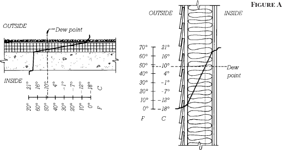
In wintertime, it is warm inside a heated building and cold outside and the inside surface of a wall or roof assembly is warm, and the outside surface is cold. Between the two surfaces, the temperature varies according to the thermal resistances of the various layers of the assembly. Because most of the insulating value of the assembly is in the insulation itself, most of the temperature change within the assembly occurs across the thickness of the insulating material (Figure A).
Water Vapor and Condensation
Water exists in three physical states, depending on its temperature and pressure: solid (ice), liquid, and vapor. Air always contains some water in the form of water vapor, an invisible gas. The higher the temperature of the air, the more water vapor it can contain. At a given temperature, the amount of water vapor the air actually contains, in proportion to the maximum amount of water vapor it can contain, is the relative humidity of the air. For example, air at 50 percent relative humidity contains half as much water vapor as it is capable of holding at that particular temperature.
If a mass of air is cooled, its relative humidity rises. The amount of water vapor in the air mass has not changed, but the ability of the air mass to hold water vapor has diminished because the air has become cooler. If the cooling of the air mass continues, a temperature will be reached at which the humidity is 100 percent. This is the temperature at which the air is fully saturated with water vapor, also known as the dew point. The dew point is different for every air mass. A roomful of very humid air has a high dew point, which is another way of saying that the air in the room would not have to be cooled very much before it reached 100 percent humidity. In comparison, a roomful of dry air has a lower dew point and can be cooled to a lower temperature before it reaches saturation.
When a mass of air is cooled below its dew point, it can no longer contain all its water vapor and some of the vapor turns to liquid. The further the air mass is cooled below this point, the less water vapor it can hold and the more vapor turns to liquid. This process of converting water vapor to liquid by cooling is called condensation.
Condensation takes place in buildings in many different ways. In winter, room air circulating against a cold pane of glass may be cooled to below its dew point, and water droplets will form on the glass. If the air is very humid, the droplets will grow in size, then run down the glass to accumulate in puddles on the window sill. If the glass is very cold, the condensate may freeze into patterns of ice crystals on the glass. In a similar fashion, on a hot, humid summer day, water vapor in the air may condense on the surface of a cold water pipe, a cool basement wall, or an ice-cold glass of lemonade. Though hidden from view, condensation can also occur within the walls, roofs, and other assemblies that enclose a building.
Water Vapor in Building Assemblies
Water vapor is a gas and exerts pressure, called vapor pressure, on the surfaces that contain it. The more water vapor an air mass contains, the greater the vapor pressure. Under wintertime heating conditions, the air inside a building is at a higher temperature and contains more water vapor than the air outside. This is especially true in areas of the building with many occupants or where cooking, wet industrial processes, bathing, or washing take place. The result is a net difference in vapor pressure acting from inside to outside, causing water vapor to diffuse outward directly through the various material layers of the enclosing assembly. If the rate of diffusion is high enough and the drop in temperature within the assembly great enough, water vapor will reach its dew point and condense within the assembly. If moisture accumulates, insulation may loose its effectiveness and materials may be damaged by rusting, mildew, decay, freeze-thaw, or other harmful processes. If water runs out of the assembly, finishes or building contents may be harmed. (Water vapor can also be carried through an assembly by air leaking through gaps in materials. This is a different mechanism than the diffusion of water vapor through materials and is discussed under the topic of air barriers on pages 800–803.)
Under summertime cooling conditions in hot, humid weather, the diffusion of water vapor through building assemblies is reversed. Water vapor is driven from the warm, damp outside air toward the cooler, drier air within. In most of North America, this summer condition is not as severe as that in winter: Differences in summer temperature and humidity between indoors and outdoors are not as great as those in winter, and the cooling season is short compared to the heating season. Where heating conditions predominate, control of water vapor in building assemblies focuses primarily on the flow of vapor from interior to exterior, though conditions of reverse, inward flow may also warrant some consideration. In areas of the American South and in the Hawaiian Islands, however, the summer condition is the more severe, and the flow of water vapor from exterior to interior is the predominant problem to be solved.
Vapor Retarder
A vapor retarder (often called, inexactly, a vapor barrier) is a material used to slow the diffusion of water vapor through a building assembly. Vapor retarders are continuous sheets or coatings made of plastic, metal foil, coated paper, or any other material resistant to the passage of water vapor.
Vapor retarders are located toward the warmer side of the insulation in a building assembly. In this position, they can restrict the diffusion of water vapor into the assembly from the side of higher vapor pressure, limiting chances for dew point conditions and condensation to occur within the assembly’s cooler portions. For buildings in most parts of North America, where winter heating conditions predominate, vapor retarders are placed toward the interior, heated side of insulation in the assembly. In humid regions where warm-weather cooling predominates within buildings, the vapor retarder should be located toward the exterior side of insulation. In relatively mild or balanced climates, or where assemblies are designed to minimize condensation conditions, a vapor retarder may not be necessary at all.
The better a material’s resistance to water vapor diffusion, that is, the lower its vapor permeance, the more effective it is as a vapor retarder. Permeance is measured in perms, defined by ASTM E96 as the passage of one grain of water vapor per hour through 1 square foot of material at a pressure differential of 1 inch of mercury between the two sides of the material (grains/hr-ft2-in. Hg). In metric units, a perm is measured in grams per second per square meter per Pascal of pressure difference (g/s-m2-Pa). One U.S. perm equals 5.72 × 10⁻⁸ metric perms. To arrive at more workable units, metric perms may also be calculated with nanograms (billionths of a gram) in place of grams. In this case, one U.S. perm equals 57.2 ng/s-m2-Pa. Model building codes generally define materials used as vapor retarders as having a U.S. perm rating of 1 (metric perm rating of 60 ng/s-m2-Pa) or less.
When evaluating vapor retarders, vapor permeance should not be confused with vapor permeability. Vapor permeability is defined as a material’s vapor permeance for a unit of thickness. For example, the vapor permeability of a particular rigid insulation may be given as 0.75 perminch. The vapor permeance of an insulation board made of this material is then found by dividing the material’s permeability by the actual thickness of the board used. For example, if the insulation board is ½ inch thick, its permeance is 1.5 perms (0.75 perm-in./0.5 inch), or if 2 inches thick, 0.375 perm (0.75 perm-in./2 inches). In metric units, vapor permeability is calculated as ng-m/Pa-s-m2, which reduces to ng/Pa-s-m.
The vapor permeance of some materials varies. Materials that absorb liquid moisture, such as plywood or the kraft paper facing found on much glass fiber batt insulation, tend to increase in permeance when damp. At least one manufacturer’s proprietary vapor retarder membrane is engineered purposely to increase in permeance under conditions of high humidity as well. Such materials can provide benefits, inhibiting vapor diffusion into the assembly under normal conditions but becoming more permeable and enhancing the ability of the assembly to dry outward if moisture accumulates within it.
Commonly used vapor retarder materials are polyethylene plastic sheet, kraft paper facing on glass fiber batt insulation, aluminum foil facing on various types of insulation, and special paint primers with low water vapor permeability. Some foam insulation materials, depending on their formulation and thickness, can also act as vapor retarders. In low-slope roof construction, where vapor retarders are frequently installed as part of the roof membrane system, vapor retarders are often made of roofing felts layered in hot asphalt or of adhered rubberized asphalt sheets (Figure B).
Vapor Retarder Usage
Vapor retarders are used in insulated building assemblies to prevent water vapor condensation within the assembly. This is most likely where an assembly is exposed to large temperature differences from one side to the other and the relative humidity is high on the warmer side. In the International Energy Conservation Code (2006), requirements for vapor retarders differ between residential and commercial building types and with building location. Generally speaking, vapor retarders are required in exterior wall and ceiling assemblies for buildings in regions of the United States where winter heating conditions predominate, that is, in roughly the upper two-thirds of the continental United States as well as Alaska. The Building Code of Canada (2005) requires vapor retarders in most insulated building assemblies.
Where vapor retarders are used, the cooler side of the assembly, opposite the vapor retarder, must be “breathable,” that is, designed so that any moisture that does find its way into the assembly can be dispersed by means of ventilation or diffusion through vapor-permeable materials. Examples of this strategy include ventilated roof systems, ventilated rainscreen cladding, and the use of vapor- permeable house wraps. Assemblies with multiple vapor-impermeable layers should be approached with caution: They can trap moisture and provide no means for the moisture to escape. A rule of thumb sometimes used for the selection of materials on the opposite side of an assembly from a vapor retarder is that they have a vapor permeance at least 10 times that of the vapor retarder itself.
Additional factors to consider in the use of vapor retarders include the following:
• The temperature and humidity conditions to which a building assembly is exposed over time are not static. A wall system designed exclusively for winter heating conditions may perform poorly when vapor migrates from the exterior inward during summer months with air conditioning in operation. Solar heating of a rain-soaked exterior cladding system can cause strong inward water vapor movement at any time of the year.
• Building assemblies must be able to dry out when wet. Water introduced into a building assembly, such as from penetrating rain or from construction with wet building materials, must have a means to escape so that the assembly can dry.
• Air barriers are also important to the control of water vapor. Under many circumstances, air leakage can transport many times greater amounts of water vapor into an assembly than can vapor diffusion. Air barriers are discussed on pages 800–803.
• Design for water vapor control should consider all components of an assembly. The permeability of exterior sheathing, cladding or roofing, provisions for ventilation, and the location and types of insulating materials within an assembly can all influence the choice and placement of vapor retarders.
For more information on the design of vapor retarders in insulated building assemblies, see the references listed at the end of this chapter.
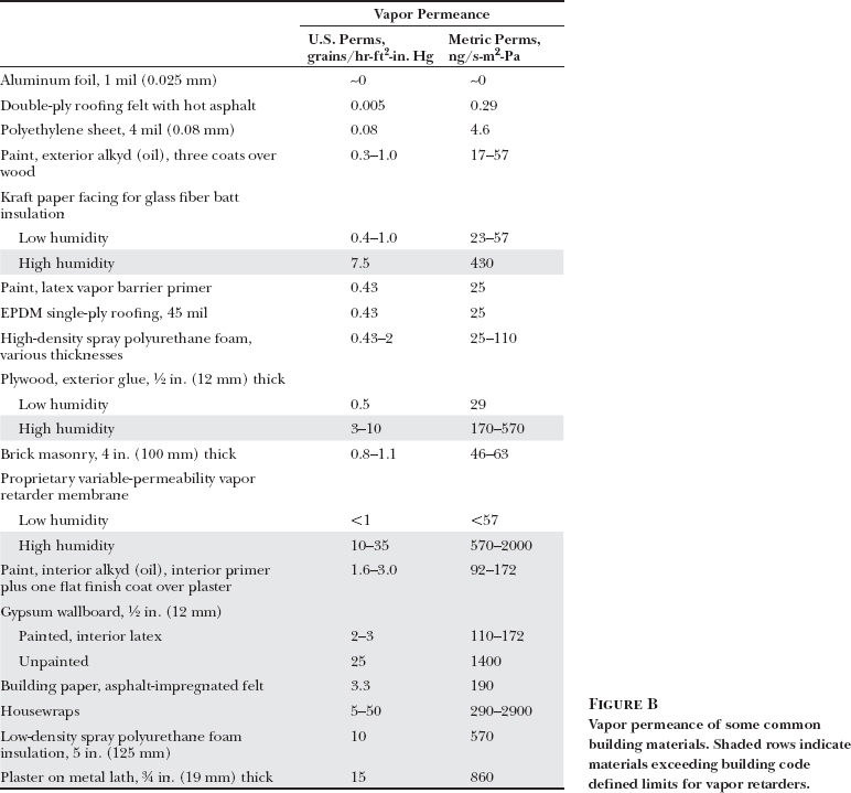
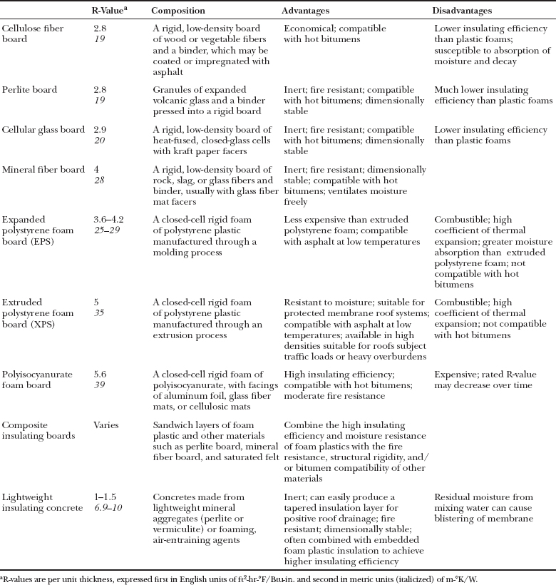
FIGURE 16.10 A comparative summary of some rigid insulating materials for low-slope roofs.
Rigid Insulating Materials for Low-Slope Roofs
An insulating material for low-slope roofs should have high thermal resistance, adequate resistance to compression, denting, gouging, moisture decay, and fire, and, if part of a hot-applied system, high resistance to melting or dissolving when hot bitumens are mopped onto it. No single material has all these virtues. Some rigid insulating materials commonly used on low-slope roofs in North America are listed in Figure 16.10, along with a summary of their advantages and disadvantages. The best choice is often a combination of materials, or a composite board that combines two or more materials into one product, to exploit the best qualities of each. A composite insulating board for installation under a built-up bituminous roof membrane might include, for example, a bottom layer of polyisocyanurate foam with high insulating value and a top layer of perlitic board resistant to hot bitumens.
If rigid insulating boards are located below the roof membrane, they may be adhered to the deck with hot asphalt or adhesives, or fastened to the deck mechanically with screws or any of a variety of fasteners made especially for the purpose. Mechanical fasteners are favored by insurance companies because they are more secure against wind uplift (Figures 16.11 and 16.12).
Lightweight insulating concrete is an economical insulating material that also creates a nailable roof deck. Formulated with lightweight aggregates or foaming, air entraining agents, this material has densities ranging from 20 to 40 lb/ft3 (320 to 640 kg/m3) compared to 145 lb/ft3 (2320 kg/m3) for conventional concrete. Lightweight concrete may be applied directly to corrugated steel decking or over rough concrete decks and can easily be tapered during installation to slope toward points of roof drainage. Thermal resistance per inch is not as high for this material as for most other types of roof insulation. However, plastic foam boards may be embedded in the insulating concrete to achieve higher insulating values within reasonable thicknesses. Lightweight concrete fill insulation contains large amounts of free water at the time it is placed. It must be cured and dried as thoroughly as possible before application of the membrane, and some form of venting to allow the escape of moisture vapor from the insulation during the life of the roof, via either topside vents or bottomside slotted metal roof decking, is usually advisable. Poured-in-place gypsum, another decking material popular in the past for forming lightweight, nailable sloping roof decks, is no longer used in new construction.
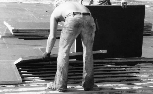
FIGURE 16.11 Workers bed rigid insulation boards in strips of hot asphalt over a corrugated metal roof deck. (Courtesy of GAF Corporation)
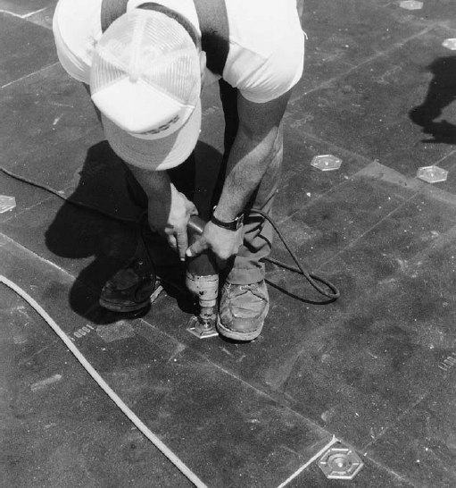
FIGURE 16.12 Screws and large sheet metal washers attach insulation more securely to a metal deck than can hot asphalt. (Courtesy of GAF Corporation)
Vapor Retarders for Low-Slope Roofs
The membrane in a protected membrane roof serves also as the vapor retarder. However, when insulation is located below the roof membrane, a separate vapor retarder is recommended in cold climates or when enclosing high-humidity interior spaces.
The most common type of vapor retarder for a low-slope roof consists of two layers of asphalt-saturated roofing felt bonded together and adhered to the roof deck with hot asphalt. Vapor retarder sheets made from factory-manufactured self-adhering bituminous membranes are also common. Polyethylene sheeting, used as a vapor retarder in many other types of construction, is seldom used in low-slope roofs because it melts at the application temperature of the hot bitumen used in many roof membranes, and it does not stand up well to the rigors of foot traffic and other construction activities that occur during roofing installation.
When a vapor retarder is included in a low-slope roof assembly, it must be located within the assembly such that it will always be warmer than the dew point of the interior air under common conditions of use. This usually means putting the vapor retarder below the insulation. However, a vapor retarder should not be installed directly over a corrugated steel deck, where it would have to bridge across the corrugations and would be vulnerable to damage until it was covered by insulation. In such cases, substrate board (thin panels of wood, gypsum board, or foam insulation) is first laid over the deck, followed by the vapor retarder and then the insulation boards. When some portion of the roof insulation is located below the vapor retarder, the designer must carefully calculate the dew point location in this assembly to be sure that the vapor retarder lies below it.
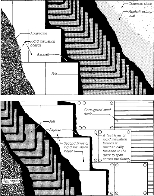
FIGURE 16.13 Two typical built-up roof constructions, as seen from above. The top diagram is a cutaway view of a protected membrane roof over a sitecast concrete roof deck. The membrane is made from plies of felt overlapped in such a way that at no location is it less than four plies thick. Rigid foam insulation boards are bedded in hot asphalt over the membrane and ballasted with stone aggregate to keep them in place and protect them from sunlight. The bottom diagram shows how rigid insulation boards are attached to a corrugated steel roof deck in two staggered layers to provide a firm, smooth base for application of the membrane. A three-ply membrane is shown. In cold climates, a vapor retarder should be installed between the layers of insulation or under the insulation over a substrate board fastened to the steel roof deck.
Membranes for Low-Slope Roofs
The membranes used for low-slope roofing fall into three categories: bituminous roof membranes, single-ply roof membranes, and fluid-applied roof membranes.
Bituminous Roof Membranes
Bituminous roof membranes are of two types, built-up or modified bitumen. A built-up roof (BUR) membrane is assembled in place from multiple layers of asphalt-impregnated roofing felt bedded in additional layers of bitumen (Figures 16.13–16.15). The felt, made from cellulose, glass, or synthetic fibers, is saturated with asphalt at the factory and delivered to the site in rolls. The bitumen is usually asphalt derived from the distillation of petroleum, but for dead-level or very low slope roofs, coal tar pitch is used instead because of its greater resistance to standing water. Polymer-modified asphalts, as described below for modified bitumen roofs, may also be used. Both asphalt and coal tar pitch are applied hot in order to merge with the saturant bitumens in the felt and form a unified, multi-ply membrane. The felt is laminated in overlapping layers (plies) to form a membrane that is two to four plies thick. The more plies used, the more durable the roof. To protect the membrane from sunlight and physical wear, a layer of crushed stone or other mineral granule aggregate is embedded in the top surface. Less commonly, a built-up roof may be made from felt plies bedded in cold-applied mastics (solvent-based asphalts), that is, compounds of asphalt and other substances applied by spray or brush at ambient temperatures and then cured through solvent evaporation.
A modified bitumen roof membrane is made from factory-manufactured sheets of polymer-modified bitumens. Modified bitumens are asphalt materials to which compounds such as atactic polypropylene (APP) or styrene-butadiene-styrene (SBS) have been added in order to increase the material’s flexibility, cohesion, toughness, and resistance to flow. Modified bitumen roof membrane sheets are also reinforced with plastic or glass fibers or fibrous mats. Sheet thickness typically ranges from 0.040 to 0.160 inch (1.0–4.0 mm).
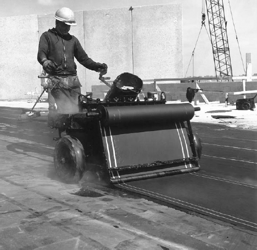
FIGURE 16.14 A base sheet of asphalt-saturated felt is installed over rigid insulation, using a machine that unrolls the felt and presses it into a layer of hot asphalt. (Courtesy of the Celotex Corporation)
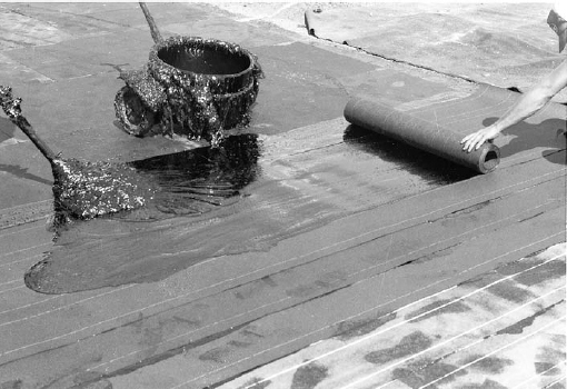
FIGURE 16.15 Overlapping layers of roofing felt are hot-mopped with asphalt to create a four-ply membrane. (Courtesy of Manville Corporation)
Like a built-up roof, modified bitumen sheets are assembled in place in overlapping layers to form a multi-ply system, usually two or three plies thick. The sheets are bonded to one another in a number of possible ways: With a torch-applied membrane, as a roofing sheet is unrolled, an open-flame apparatus is used to thermally fuse the underside of the sheet to the top surface of the substrate or underlying sheet. A hot-mopped membrane relies on the application of hot asphalt to bond the sheets, a cold process or cold-applied adhesive membrane uses liquid adhesives, and a self-adhered membrane relies on factory-applied adhesives (Figures 16.16).
The top or cap sheet in a modified bitumen roof is surfaced with mineral granules, thin metallic laminates, or asphaltic or elastomeric coatings for greater resistance to ultraviolet deterioration, wear, and fire (Figure 16.17). Cap sheets with reflective white coatings that comply with cool roof standards are also available. In comparison to built-up roofs, modified bitumen roofs combine the toughness and redundancy of multi-ply field application with the improved material qualities of factory-manufactured sheets. Built-up and modified bitumen systems may also be combined with a modified bitumen cap sheet applied over several plies of built-up roofing to create a hybrid membrane bituminous roof. Bituminous roofing systems account for approximately 40 percent of the market for low-slope roofing membranes, with the larger portion of this share belonging to modified bitumen systems.
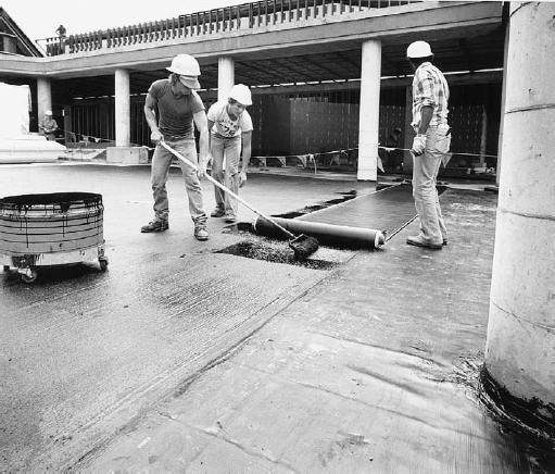
FIGURE 16.16 Roofers bond a polymer-modified bitumen membrane to a concrete deck with a cold-applied adhesive. The seams will be heat-fused together. (Courtesy of Koppers Company, Inc.)
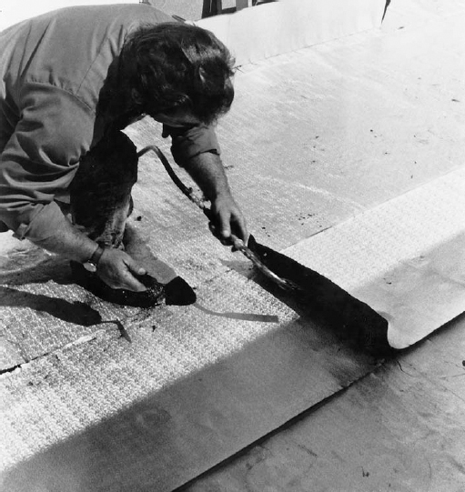
FIGURE 16.17 A roofer heat-fuses a seam between two sheets of an aluminum-faced modified bitumen membrane. The aluminum foil protects the membrane from the sun and reflects solar heat from the roof. (Courtesy of Koppers Company, Inc.)
Single-Ply Roof Membranes
Single-ply roof membranes are a diverse and seemingly ever-evolving group of sheet materials that are applied to the roof in a single layer (Figure 16.18). Compared to bituminous roof membranes, they require less on-site labor, and especially in comparison to built-up roof membranes, they are more elastic and therefore less prone to cracking or tearing as they age. Common membrane thicknesses vary from 0.035 to 0.120 inch (0.9 to 3.0 mm), depending on the membrane material type and the requirements of the roofing application. Single-ply membranes may be affixed to the roof deck by adhesives, the weight of ballast, fasteners concealed in the seams between sheets, or, if the sheets are sufficiently flexible, with the use clever mechanical attachments that need not penetrate the membrane (Figures 16.19–16.21).
The materials used for single-ply membranes fall into two groups: thermoplastic and thermosetting. Thermoplastic materials can be softened by the application of heat and may be joined at the seams by heat (or solvent) welding. This welding process, which fully fuses one sheet to another, results in seams between sheets that are reliable, strong, and long-lasting. Thermosetting materials, also sometimes referred to as elastomerics, have a more tightly linked molecular structure and cannot be softened by heat. Thermosetting sheets must be joined at the seams by liquid adhesives or pressure-sensitive tapes, which have not always proved as reliable as the welded seams in thermoplastic membranes. Single-ply membranes, unlike multi-ply bituminous membranes, have no redundancy. Even a small defect in the joining of sheets can result in significant leakage through the membrane. (See pages 758–761 for more information about the difference between thermoplastic and thermosetting plastics.)
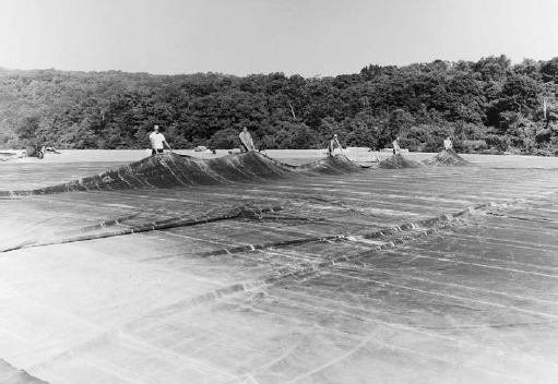
FIGURE 16.18 Workers unfold a large single-ply roof membrane. (Courtesy of Carlisle SynTec Systems)
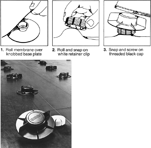
FIGURE 16.19 AND 16.20 A proprietary nonpenetrating attachment system for a single-ply roof membrane. (Courtesy of Carlisle SynTec Systems)
The most commonly used thermoplastic roof membrane materials are polyvinyl chloride (PVC) and thermoplastic polyolefin (TPO). PVC roof membranes, made of PVC resins, plasticizers, stabilizers, and reinforcing fibers or fabrics, have a track record of successful performance established over many decades. They are available in various colors, including reflective white for cool roofs. However, concerns over the production of toxic chemicals (in particular, dioxin, a known carcinogen) during the manufacture and disposal of PVC have led to debate over the appropriateness of PVC for use as a construction material. No consensus has yet emerged, and as PVC manufacturers continue to improve their manufacturing processes and institute materials recycling programs, the pros and cons of this issue are likely to continue to evolve for the foreseeable future. TPO roof membranes are relatively new to the North American low-slope roofing market. They are made from blends of polyethylene, polypropylene, and ethylene-propylene rubber polymers reinforced with fibers or fabrics. TPO membranes exhibit good resistance to heat and ultraviolet (UV) radiation, characteristics more commonly associated with thermosetting membranes, but as thermoplastics, their seams can be heat welded. They are also available in a broad range of colors. PVC and TPO together account for approximately 20 percent of the market for low-slope roofing materials. Other, less widely used thermoplastic roof membrane materials include ketone ethylene ester (KEE) and a class of materials referred to as “PVC alloys” or “PVC compounded thermoplastics,” made from various blends of PVC and other polymers.
The most commonly installed thermosetting roof membrane material is ethylene propylene diene monomer (EPDM), a synthetic rubber that may or may not include fiber or fabric reinforcing. EPDM has a highly stable chemical structure with excellent resistance to ozone, heat, UV radiation, and weathering. It is most commonly black in color but is also available in cooler white from some manufacturers. Since EPDM cannot be heat welded, seaming is performed with tapes or adhesives. Like PVC, EPDM has a many-decades-long track record of successful performance. It is the most widely used material in North America for low-slope roofing of any type, accounting on its own for more than one-third of the market for such applications. Other thermosetting roof membrane materials include chorosulfonated polyethylene (CSPE) and polyisobutylene (PIB).
Fluid-Applied Roof Membranes
Fluid-applied roof membranes are used primarily for domes, shells, and other complex shapes that are difficult to roof by conventional means. Such shapes are often too flat on top for shingles but too steep on the sides for built-up roof membranes, and if doubly curved, they are difficult to cover with preformed sheets. Fluid-applied membranes are installed in liquid form with a roller or spray gun, usually in several coats, and cure to form a rubbery membrane. Materials applied by this method include neoprene (with a protective layer of CSPE), silicone, polyurethane, butyl rubber, and asphalt emulsion.
Fluid-applied membranes are also used as a waterproofing layer over sprayed-on polyurethane foam insulation in proprietary roofing systems designed for surfaces that are hard to fit with flat sheets of insulation and membrane. These systems are also a convenient means for adding thermal insulation and a new roof membrane over existing deteriorated built-up roofs on any shape of building.
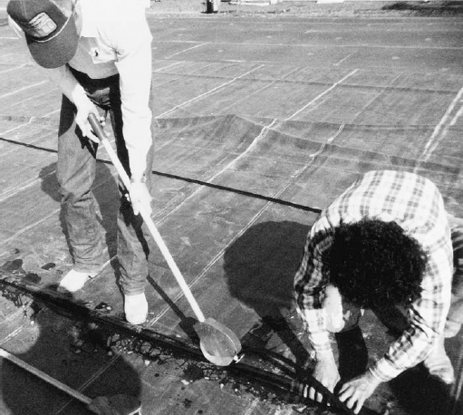
FIGURE 16.21 Another proprietary nonpenetrating attachment system folds the membrane into a continuous slot, where it is held by a synthetic rubber spline that is inserted with a wheeled tool. (Courtesy of Firestone)
Membranes for low-slope roofing can have life expectancies ranging from 10 to 30 years, depending on the membrane material and thickness, the geographic location of the roof, its exposure to extremes of temperature and UV radiation, and the quality of the roof’s installation and maintenance.
Ballasting and Traffic Decks
Roof membranes may be covered after installation with a ballast of loose, rounded stone aggregate ranging in size from 1½ to 2½ inches (38 to 64 mm) in diameter or with precast concrete paver blocks (Figures 16.8 and 16.22). The ballast serves to hold the membrane down against wind uplift, and it protects the membrane from ultraviolet light and physical wear. It may also contribute to the fire resistance of the roof covering.
Traffic decks are installed over flat roof membranes for walks, roof terraces, and sometimes driveways or parking surfaces. Two different details are used: In one, low blocks of plastic or concrete are set on top of the roof membrane to support the corners of heavy square paving stones or slabs with open joints (Figure 16.23). In the other, a drainage layer of gravel or no-fines concrete (a very porous concrete whose aggregate consists solely of coarse stone of a single size) is leveled over the membrane, and open-jointed paving blocks are installed on top. In either detail, water falls through the joints in the paving and is caught and drained away by the membrane below. Notice that the membrane is not pierced in either detail.
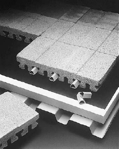
FIGURE 16.22 This ballasting system uses special concrete blocks that are joined by tubular plastic splines. The grooves in the bottoms of the blocks are designed to facilitate drainage of water from the membrane. The blocks are made with lightweight aggregate, so they contribute to the thermal insulation of the roof. (Insulating roof ballast with variable interlock feature © National Concrete Masonry Association, 1988)
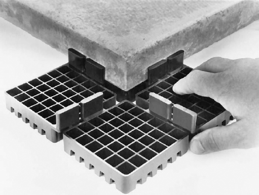
FIGURE 16.23 A proprietary system for supporting stone or precast concrete paving blocks over a low-slope roof membrane permits the use of a low-slope roof as an outdoor terrace. Each high-density polyethylene pedestal supports the adjacent corners of four paving blocks. The vertical spacer fins on the pedestal provide a uniform drainage space between the blocks. Matching polyethylene leveling plates (not shown) can be placed over the pedestal to compensate for irregularities in the roof surface. (Photo courtesy of Envirospec, Inc., Buffalo, New York)
Edge and Drainage Details for Low-Slope Roofs
Some typical details of low-slope roofs are presented in Figures 16.24–16.33. All are shown with built-up roof membranes, but details for single-ply membranes are similar in principal.
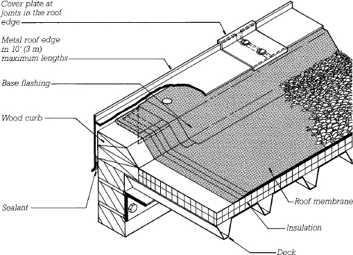
FIGURE 16.24 A roof edge for a conventional built-up roof. The membrane consists of four plies of felt bedded in asphalt with a gravel ballast. The base flashing is composed of two additional plies of felt that seal the edge of the membrane and reinforce it where it bends over the curb. The curb directs water toward interior drains or scuppers rather than allowing it to spill over the edge. The exposed vertical face of the metal roof edge is called a fascia.
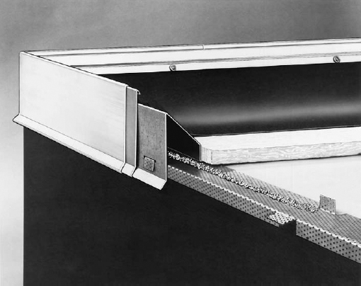
FIGURE 16.25 A proprietary roof edge system for low-slope roofs. The perforated metal strip is fastened to the roof with a mastic adhesive that oozes through the perforations to create a tighter bond. When the adhesive has hardened, a galvanized steel curb is fastened in place with the tabs of perforated metal and an aluminum roof edge is hooked on, with a backup piece at the end joints as shown to prevent leakage. Lastly, the roof edge and the membrane are locked in place simultaneously by installing a clamping strip that engages the hook on the top of the aluminum roof edge. The clamping strip is held in place by screws that pass through the edge of the membrane into the galvanized curb, as seen at the top of the photograph. (Product of W. P. Hickman Company, Asheville, North Carolina)
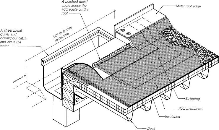
FIGURE 16.26 Detail of a scupper. The curb is discontinued to allow water to spill off the roof into a gutter and downspout. Additional layers of felt, called stripping, seal around the sheet metal components. Most roofs use interior drains (Figure 16.31) as their primary means of drainage, with scuppers more frequently used as secondary drainage to limit ponding in the case of a clog in the primary drain.
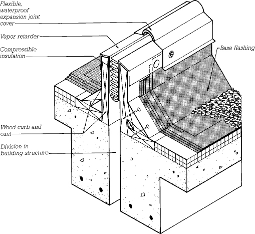
FIGURE 16.27 A building separation joint in a low-slope roof. Large differential movements between the adjoining parts of the structure can be tolerated with this type of joint because of the ability of the flexible joint cover to adjust to movement without tearing. High curbs keep standing water away from the edge of the membrane, which is sealed with a two-ply base flashing.
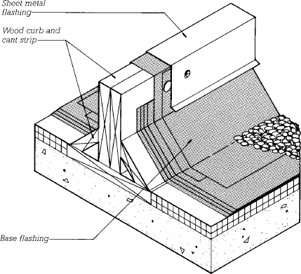
FIGURE 16.28 An area divider is designed to allow for some movement only in the membrane itself, not in the entire structure. It is used to subdivide a very large membrane to allow for thermal movement.
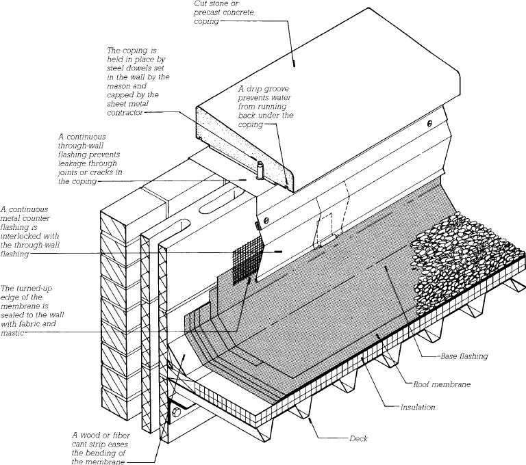
FIGURE 16.29 A parapet—a low wall that projects above the roof edge—with conventional counterflashing and coping. Cant strips, as seen in this and many other illustrated details in this chapter where the roof membrane turns up onto a vertical surface, are commonly used with bituminous roofing, in which the less flexible membranes and multiple plies cannot easily make a sharp right-angle bend. Single-ply membranes typically do not require cant strips under such conditions.
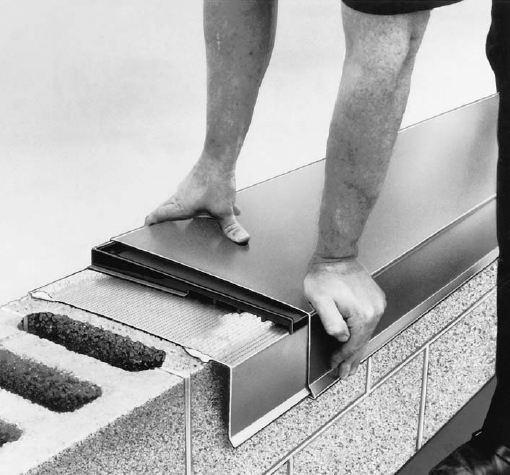
FIGURE 16.30 A proprietary parapet coping system. The perforated metal channel is fastened to the masonry with a mastic adhesive. Sections of metal coping are snapped over the channel, with a special pan element beneath the joints to drain leakage. (Product of W. P. Hickman Company, Asheville, North Carolina)
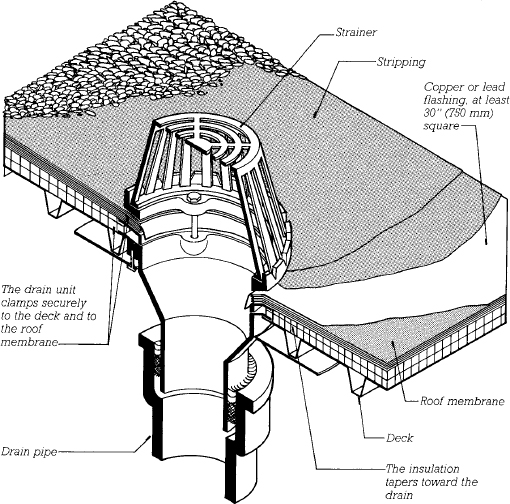
FIGURE 16.31 A conventional cast iron interior roof drain for a low-slope roof. Two plies of felt stripping seal around the sheet metal flashing.
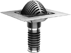
FIGURE 16.32 A proprietary single-piece roof drain made of molded plastic. (Product of W. P. Hickman Company, Asheville, North Carolina)
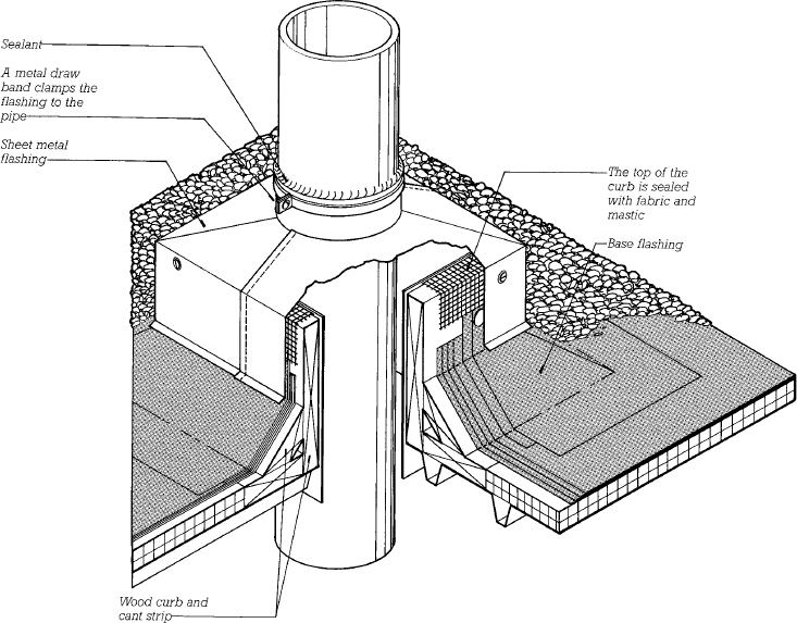
FIGURE 16.33 A roof penetration for a plumbing vent stack. Notice how this and all the previous edge and penetration details for a flat roof use the curb, cant strip, and stripping to keep standing water away from the edge of the membrane.
Structural Panel Metal Roofing for Low-Slope Roofs
Manufacturers of prefabricated metal building systems have developed proprietary systems of metal roofing panels that can be used as low-slope roofs at pitches as shallow as ¼:12 (1 in 48, or about 2 percent). These systems can be applied not only to prefabricated metal buildings but to buildings constructed of other materials as well (Figures 16.34–16.36). They are called structural panel metal roofing because the folded shape of the metal roofing gives it sufficient stiffness to support itself and normal snow loads between purlins without the need for a structural deck beneath. This name also distinguishes it from architectural sheet metal roofing, the traditional forms of metal roofing that are not self-supporting. Architectural sheet metal roofing is utilized largely on steep roofs and is described later in this chapter.
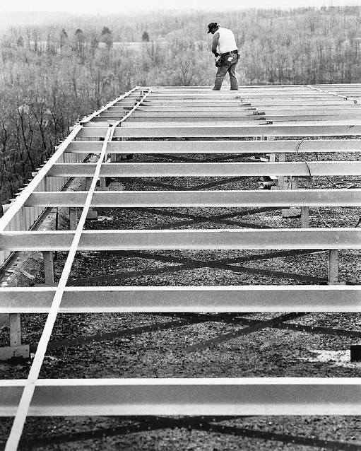
FIGURE 16.34 As a first step in reroofing a building with a structural metal roof, steel Z-purlins are erected over the old roof on tubular metal posts. (Courtesy of Metal Building Manufacturers Association)
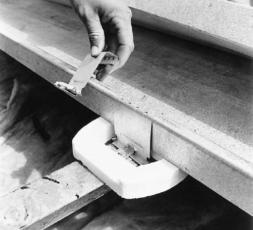
FIGURE 16.35 A proprietary metal clip is used to fasten the metal roofing sheets to the Z-purlins while allowing for thermal movement in the sheets. The plastic foam collar avoids thermal bridging. (Courtesy of Metal Building Manufacturers Association)
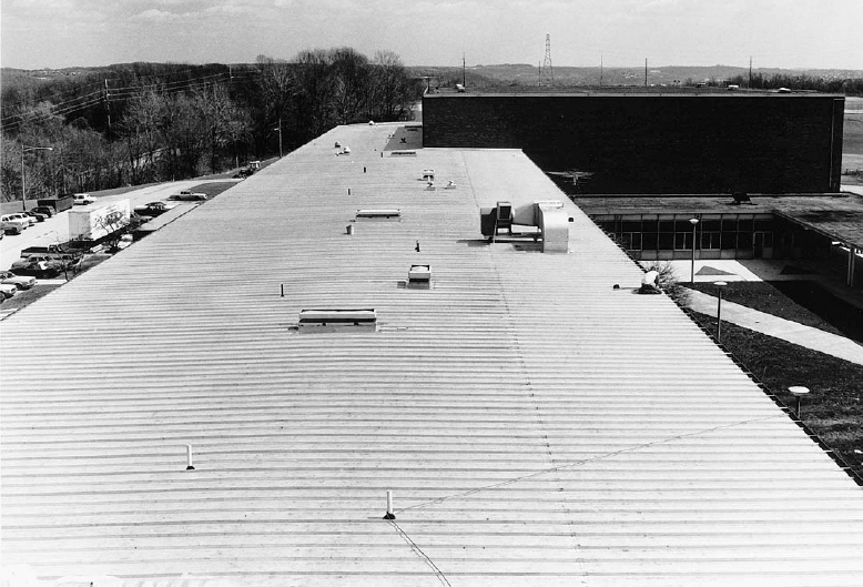
FIGURE 16.36 The completed structural metal roof has a slope of only ½:12 (1:48). The numerous penetrations for plumbing vents, air vents, and ductwork are typical of low-slope roofs. (Courtesy of Metal Building Manufacturers Association)
Leave a Reply