
Partition Framing
Partitions that will be finished in plaster or gypsum board are usually framed with wood or metal studs (Figures 23.1–23.3). Framing with wood studs is permitted by the building code only in buildings of certain combustible construction types, including Types III and V. Partitions in buildings of Type I or Type II (noncombustible) construction must be framed with metal studs. Partitions in Type IV, Heavy Timber construction, must either be framed with metal studs or constructed with wood members assembled into solid, laminated partitions as specified in the code. With certain limitations, fire-retardant-treated wood is also permitted for partition framing in Types I, II, and IV construction.
Metal partition framing is directly analogous to wood light framing, but constructed of light gauge steel studs and runner channels made of galvanized steel sheet metal 0.018 to 0.054 inch (0.45-1.37 mm) thick (Figure 12.2). Light gauge steel members and framing methods are detailed in Chapter 12. Because of its noncombustibility, metal partition framing is permitted in all building code construction types.
If plaster or gypsum board surfaces are to be applied over a masonry wall, they may be spaced away from the wall with either wood or metal furring strips (Figures 23.4–23.6). Furring allows for the installation of a flat wall finish over an irregular masonry surface, and provides a concealed space between the finish and the masonry for installing plumbing, wiring, and thermal insulation.
Fireblocking of Combustible Concealed Spaces
Building codes require that concealed hollow spaces within combustible partition or wall assemblies (that is, partitions framed with wood studs, but not those framed with light gauge steel) be internally partitioned into spaces sufficiently small in size to limit the ability of fire to travel undetected within such spaces. Materials used for this purpose are called fire-blocking and may consist of solid lumber, plywood, OSB, particleboard, gypsum board, cement fiberboard, or even glass fiber insulation batts when securely installed. The International Building Code requires fireblocking in combustible concealed spaces at all ceiling and floor levels, as well as at horizontal intervals not exceeding 10 feet (3 m), such as may occur behind furred finish systems or within double stud walls constructed to accommodate plumbing piping or to improve acoustical separation.
Plaster
Plaster is a generic term that refers to any of a number of cementlike substances that are applied to a surface in paste form and then harden into a solid material. Plaster may be applied directly to a masonry surface or, more generally, to any of a group of plaster bases known collectively as lath (rhymes with “math”). Plastering began in prehistoric times with the smearing of mud over masonry walls or over a mesh of woven sticks and vines to create a construction known as wattle and daub, the wattle being the mesh and the daub the mud. The early Egyptians and Mesopotamians developed finer, more durable plasters based on gypsum and lime. Portland cement plasters evolved in the 19th century. It is from these latter three materials—gypsum, lime, and portland cement—that the plasters used in buildings today are prepared.
Gypsum Plaster
Gypsum is an abundant mineral in nature, a crystalline hydrous calcium sulfate. It is quarried, crushed, dried, ground to a fine powder, and heated to 350 degrees Fahrenheit (175°C) in a process known as calcining to drive off about three-quarters of its water of hydration. The calcined gypsum, ground to a fine white powder, is known as plaster of Paris. When plaster of Paris is mixed with water, it rehydrates and recrystallizes rapidly to return to its original solid state. As it hardens, it gives off heat and expands slightly.
Gypsum is a major component of interior finish materials in most buildings. It has but one major disadvantage—its solubility in water. Among its advantages are that it is durable and light in weight compared to many other materials. It resists the passage of sound better than most materials. It has a very fine grain, is easily worked in either its wet or dry state, and can be fashioned into surfaces that range from smooth to heavily textured. But above all it is inexpensive, and it is highly resistant to the passage of fire.

FIGURE 23.1 Partitions of light gauge steel studs, at the left, and open-truss wire studs on the right. The light gauge steel studs are assembled with self-drilling, self-tapping screws and may be used with any type of lath or panel. Open-wire truss studs are no longer used in new construction but may still be found in older buildings undergoing renovation. They were made specifically to minimize the need for screw fasteners. Studs were secured at their bottom ends into notches in the bottom track, and at their tops, with metal shoes tied with wire. Metal lath was attached with wire, and gypsum lath with special metal clips.
FIGURE 23.2 Attaching a runner to a concrete floor using powder-driven fasteners. The gun explodes a small charge of gunpowder to drive a steel pin through the metal and into the concrete to make a secure connection. (Courtesy of United States Gypsum Company)
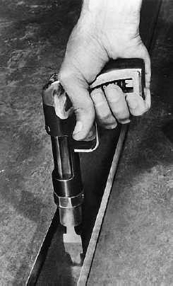
FIGURE 23.3 Inserting studs into the runners to frame a partition of light gauge steel studs. The cutouts in the webs of the studs provide a passage for electrical conduits. On the right side of the photograph, a stack of gypsum board awaits installation. (Courtesy of United States Gypsum Company)
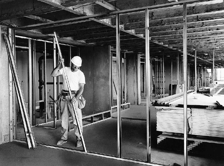
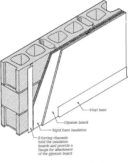
FIGURE 23.4 A furred gypsum board finish over a concrete block wall. The Z-furring channels are attached to the masonry with powder-driven fasteners. The plastic foam insulation is tucked in behind the flange of the channel, and the gypsum board is screwed to the face of the flange. Long slots punched from the web of the channel (not visible in this drawing) help to reduce the thermal bridging effect of the Z-furring channel.

FIGURE 23.5 A furred gypsum board finish using a standard hat-shaped metal furring channel (hat channel).
When a gypsum building component is subjected to the intense heat of a fire, a thin surface layer is calcined and gradually disintegrates. In the process, it absorbs considerable heat and gives off steam, both of which cool the fire (Figure 23.7). Layer by layer, the fire works its way through the gypsum, but the process is slow. The uncalcined gypsum never reaches a temperature more than a few degrees above the boiling point of water, so areas behind the gypsum component are well protected from the fire’s heat. Any required degree of fire resistance can be created by increasing the thickness of the gypsum as necessary. The fire resistance of gypsum can also be increased by adding lightweight aggregates to reduce its thermal conductivity and by adding reinforcing fibers to retain the calcined gypsum in place as a fire barrier.
For use in construction, calcined gypsum is carefully formulated with various admixtures to control its setting time and other properties. Gypsum plaster is made by mixing the appropriate dry plaster formulation with water and an aggregate, either fine sand or a lightweight aggregate such as perlite or vermiculite. Because of its expansion during setting, gypsum plaster is very resistant to cracking.
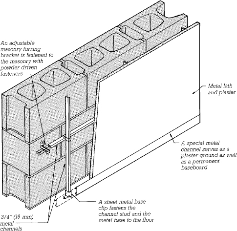
FIGURE 23.6 A furred plaster finish using adjustable furring brackets. Each bracket has a series of teeth along its upper edge so that a metal channel can be wired securely to it in any of a number of positions, allowing the lather to produce a flat wall regardless of the surface quality of the masonry.
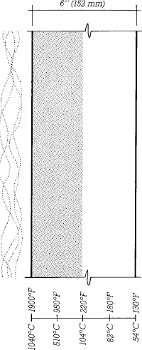
FIGURE 23.7 The effect of fire on gypsum, based on data from Underwriters Laboratories, Inc. After a 2-hour exposure to heat following the ASTM E119 time–temperature curve, less than half of the gypsum on the side toward the fire, shown here by shading, has calcined. The portions of the gypsum to the right of the line of calcination remain at temperatures below the boiling point of water.
CONSIDERATIONS OF SUSTAINABILITY IN GYPSUM PRODUCTS
Sources of Gypsum
• Naturally occurring gypsum is not renewable, but it is plentiful and widely distributed geographically.
• The majority of newly extracted gypsum is quarried in surface mines, with attendant risks of loss of wildlife habitat, surface erosion, and water pollution, as well as the problem of disposing of overburden and mine tailings.
• There is increasing use of synthetic gypsum, material recovered from power plant flue gases that would otherwise be sent to landfills, in the manufacture of gypsum construction materials. According to the Gypsum Association, approximately 1.5 million tons (1.4 million metric tons) of synthetic gypsum is used annually to produce about 7 percent of the U.S. construction industry’s calcined gypsum. Some synthetic gypsums, however, contain toxic byproducts from the manufacturing processes in which they are produced and cannot be safely recycled into new construction materials.
Gypsum Products Manufacturing
• The calcining of gypsum involves temperatures that are not much higher than the boiling point of water, which means that the embodied energy of gypsum is relatively low, about 1200 BTU per pound (2.8 MJ/kg) for plaster and 2600 BTU per pound (6.0 MJ/kg) for gypsum board.
• The calcining process emits particulates of calcium sulfate, an inert, benign chemical, as dust.
• The paper faces of gypsum board are composed primarily of recycled newspapers.
• Some manufacturers produce gypsum board products made with as much as 95 percent recycled materials, including synthetic gypsum and recycled postconsumer waste paper.
Gypsum Products on the Building Site
• Approximately 15 million tons (14 million metric tons) of gypsum board are manufactured annually in the United States. On a typical construction site, about 10 to 12 percent of this material becomes waste.
• Gypsum board waste generated during construction can be minimized by sizing walls and ceilings to make efficient use of whole boards or by ordering custom-sized boards for nonstandard-size surfaces.
• Gypsum board scrap can be permanently stored in the hollow cavities of finished walls, eliminating disposal and transportation costs and reducing the amount of material destined for landfills (though care must be taken not to create interference with the pulling of electrical wires at a later date).
• Some dust is generated by the cutting and sanding of gypsum board and plaster. This dust has not been tied to any specific illnesses, but it is a nuisance and a source of discomfort until the work is done and all the dust has been swept up and removed from the building. Remodeling and demolition also create large quantities of gypsum dust.
• Most installed gypsum products have extremely low emissions. Some joint compounds, however, may also be sources of emissions.
• Additives used in the manufacture of moisture-resistant and fire-resistant gypsum board are potential sources of volatile organic compound (VOC) emissions.
• Paints, wallcovering adhesives, and other products used to finish gypsum surfaces can be significant emitters of VOCs, and thus require care in selection and specification.
Gypsum Disposal and Recycling
• Gypsum board waste can be recycled back into the manufacture of new gypsum board products. Current efforts limit recycled content to no more than 15 or 20 percent, due to the amount of paper waste that can be safely introduced into the new gypsum without impairing its fire resistance.
• Gypsum board waste from the demolition of older buildings may be contaminated with nails, drywall tape, joint compound, and paint. Gypsum board demolished from buildings constructed prior to 1978 may be coated with lead-based paint. These foreign materials must be removed from the waste; their presence may limit the material’s recycling potential.
• Gypsum board waste can be used as a soil amendment and plant nutrient. With the recent advent of mobile grinders, construction site recycling of gypsum board waste for use as a soil amendment on the same building site is now feasible.
• Gypsum is an ingredient in many manufacturing and industrial processes. Studies and small-scale tests currently underway to identify potential uses of gypsum board waste in such processes are likely to lead to additional recycling opportunities in the future.
Gypsum plasters are manufactured in accordance with ASTM C28 and fall into two general categories: base-coat plasters, used for the underlying preparatory coats of a plaster application (as explained below), and finish-coat plasters. Base coat plasters are provided either mill-mixed, also called ready-mixed, with aggregate added at the manufacturing plant, or neat, for use with aggregate added at the job site. The more common basecoat gypsum plasters are:
• Ordinary gypsum plaster, in various formulations suitable for either hand or machine application
• Wood-fibered gypsum plaster, gypsum plaster blended with chopped wood fibers for lighter weight, and greater strength and fire resistance
• Lightweight gypsum plaster with perlite or vermiculite aggregate, for lighter weight and greater fire resistance
• High-strength base-coat plaster, for use under high-strength finish coats
Finish-coat plasters are typically a blend of gypsum plaster and lime. The lime provides superior workability and finishing qualities, while the gypsum provides greater hardness and strength and prevents shrinkage cracking. (For more information about the manufacture of lime and its use in plasters, see Chapter 8.) Common finish-coat plasters include:
• Ready-mixed finish plaster, with factory-blended lime and other ingredients
• Gauging plaster, gypsum plaster for job-site mixing with hydrated (prewetted on the job site) finishing lime (also called lime putty)
• High-strength gauging plaster, formulated to produce a finish plaster with higher compressive strength
• Keenes cement, a proprietary gauging plaster that produces an exceptionally dense, crack-resistant, low-absorbency finish
• Molding plaster, a fast-setting, fine-textured material for molding plaster ornament and running cornices (see the sidebar on pages 902 and 903)
Retarders and accelerators can also be added to plaster mixes on the job site to adjust the setting time to job-site temperature and humidity conditions.
Portland Cement Plasters
Portland cement–limeplaster, also known as stucco, is similar to masonry mortar. It is used where the plaster is likely to be subjected to moisture, as on exterior wall surfaces or in commercial kitchens, industrial plants, and shower rooms. Because freshly mixed stucco is not as buttery and smooth as gypsum and lime plasters, it is not as easy to apply and finish. It shrinks slightly during curing, so it should be installed with frequent control joints to regulate cracking.
Plastering
Plaster can be applied either by machine or by hand. Machine application is essentially a spraying process (Figure 23.8). Hand application is done with two very simple tools: a hawk in one hand to hold a small quantity of plaster ready for use and a trowel in the other hand to lift the plaster from the hawk, apply it to the surface, and smooth it into place (Figures 23.9, 23.17, and 23.21). Plaster is transferred from the hawk to the trowel with a quick, practiced motion of both hands, and the trowel is moved up the wall or across the ceiling to spread the plaster, much as one uses a table knife to spread soft butter. After a surface is covered with plaster, it is leveled by drawing a straightedge called a darby across it, after which the trowel is used again to smooth the surface.
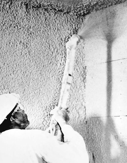
FIGURE 23.8 Spray applying a scratch coat of plaster to gypsum lath. (Courtesy of United States Gypsum Company)
Lathing
Until a few decades ago, the most common form of lath consisted of thin strips of wood nailed to wood framing with small spaces left between the strips to allow keying of the plaster. Most lath today is made of either expanded metal or preformed gypsum boards. The skilled tradesperson who applies lath and trim accessories is known as a lather.
Expanded metal lath is made from thin sheets of steel that are slit and stretched in such a way as to produce a mesh of diamond-shaped openings (Figure 23.10). It is applied to light gauge steel studs with self-drilling, self-tapping screws or to wood studs with large-headed lathing nails. Lath used with portland cement stucco is galvanized to deter corrosion.
Gypsum lath is made in gypsum board sheets (see below) 16 by 48 inches (406 × 1220 mm) and ⅜ inch (9.5 mm) thick. It consists of sheets of hardened gypsum plaster faced with outer layers of a special absorbent paper to which fresh plaster readily adheres and inner layers of water-resistant paper to protect the gypsum core. Gypsum lath is attached to steel or wood studs with screws (Figure 23.11). Gypsum lath cannot be used as a base for gauged gypsum-lime finish plasters or portland cement stucco, as these materials will not bond adequately to the paper facing.
Veneer plaster base (gypsum veneer base) is a paper-faced gypsum board that comes in sheets 4 feet (1220 mm) wide, 8 to 14 feet (2440–4270 mm) long, and ½ or ⅝ inch (13–16 mm) thick. It is screwed to wood or steel studs, or nailed to wood studs, and used as a base specifically for the application of gypsum veneer plaster (discussed below).
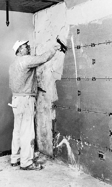
FIGURE 23.9 Applying a scratch coat over gypsum lath with a hawk (a corner of which is visible behind the plasterer’s stomach) and trowel. Notice the wire clips that hold the lath to the open-truss studs and the sheet metal clips that strengthen the end joints between panels. The end joints do not occur over studs. (Courtesy of United States Gypsum Company)

FIGURE 23.10 Five types of expanded metal lath as manufactured by the United States Gypsum Company. (a) General-purpose diamond-mesh expanded metal lath. (b) Self-furring diamond-mesh metal lath. Dimples in the lath space it away from solid sheathing behind to allow plaster to key through the openings in the mesh. (c) Paper-back lath, used for backup walls beneath ceramic tile and for exterior stucco. (d) Four-mesh Z-riblath is stiffer than ordinary diamond-mesh lath, making it suitable for ceilings. (e) Three-eighths-inch (10-mm) riblath has V-shaped ribs for exceptional rigidity; it is used for ceilings or concrete formwork where supports are widely spaced. (Courtesy of United States Gypsum Company)
Various lathing trim accessories, most frequently made of galvanized steel, are used at the edges of a plaster surface to make a neat, durable edge or corner (Figure 23.12). These are installed by the lather at the same time as the lath. In very long or tall plaster surfaces, metal control joint accessories are mounted over seams in the lath at predetermined intervals to control cracking. Trim accessories are also designed to act as lines that gauge the proper thickness and plane of plaster surfaces. A straightedge may be run across them to level the wet plaster. In this role, the trim accessories are known collectively as grounds. Trim accessories are made in several different thicknesses to match the required plaster thicknesses over the different types of lath.
In lathing I was pleased to be able to send home each nail with a single blow of the hammer, and it was my ambition to transfer the plaster from the board to the wall neatly and rapidly. . . . I admired anew the economy and convenience of plastering, which so effectually shuts out the cold and takes a handsome finish. . . . I had the previous winter made a small quantity of lime by burning the shells of the Unio fluviatilis, which our river affords. . . .
Henry David Thoreau, Walden, 1854.
Trim accessories are also produced as extrusions of plastic or aluminum. The aluminum accessories and some of the plastic ones are designed for improved precision and appearance when used in innovative details for bases, edges, and shadow lines in plaster walls.
Plaster Systems
Plaster Over Expanded Metal Lath Plaster is applied over expanded metal lath in three coats (Figure 23.13). The first, called the scratch coat, is troweled on rather roughly and cannot be made completely flat because the uncoated lath moves in and out considerably under the pressure of the trowel. This first coat is scratched while still wet, using a notched darby, a broom, or a special rake, to create a rough surface to which the second coat can bond mechanically (Figure 23.14).
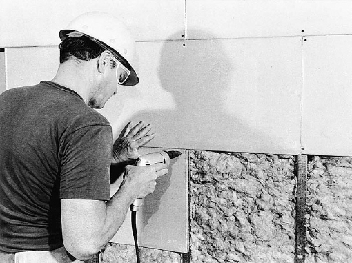
FIGURE 23.11 Installing gypsum lath over light gauge steel studs with self-drilling, self-tapping screws. The electric screw gun disengages automatically from the screw head when the screw has reached the proper depth. (Courtesy of United States Gypsum Company)
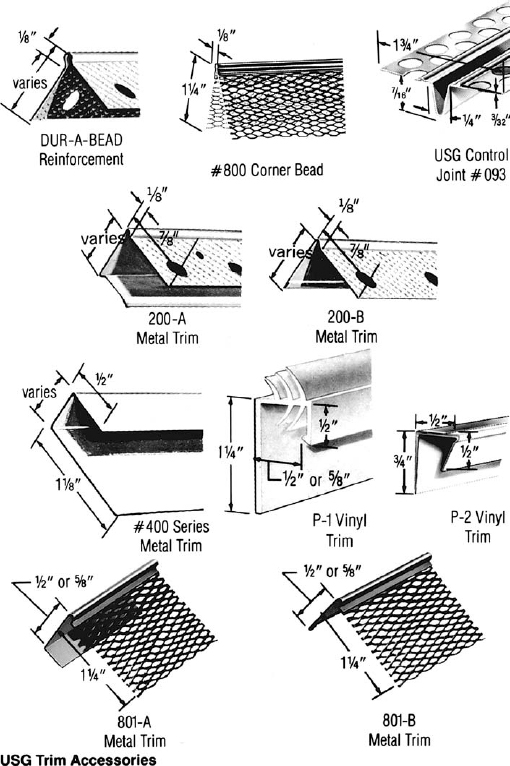
FIGURE 23.12 Trim accessories for lath and plaster construction, as manufactured by the United States Gypsum Company. (Courtesy of United States Gypsum Company)

USG Corner Beads, Trim, Control Joints
description
USG Corner Beads and Trim, made from top-quality galvanized steel, enjoy the industry’s top acceptance because of their dependability and continual improvement in design. Corner beads are available in 8 and 10-ft. lengths, metal trim in 7 and 10-ft. lengths, casing beads in 7, 8 and 10-ft. lengths.
1-A Expanded Corner Bead has 2⅞″ wide expanded flanges that are easily flexed. Preferred for irregular corners. Provides increased reinforcement close to nose of bead. Made from galvanized steel or zinc alloy for exterior applications.
X-2 Corner Bead has full 3¼″ flanges easily adjusted for plaster depth on columns. Ideal for finishing corners of structural tile and rough masonry. Has perforated stiffening ribs along expanded flange.
4-A Rexible Corner Bead is an economical general purpose bead. By snipping flanges, this bead may be bent to any curved design (for archways, telephone niches, etc.).
800 Corner Bead gives ![]() ″ grounds needed for one-coat veneer finishes. Approx. 90 keys per lin. in. provide superior bonding and strong, secure corners. The 1¼″ fine-mesh flange eliminates shadowing, is easily nailed or stapled.
″ grounds needed for one-coat veneer finishes. Approx. 90 keys per lin. in. provide superior bonding and strong, secure corners. The 1¼″ fine-mesh flange eliminates shadowing, is easily nailed or stapled.
900 Corner Bead is used with two-coat veneer systems, gives ![]() grounds. Its 1¼″ fine-mesh flange can be either stapled or nailed. Provides superior plaster key and eliminates shadowing.
grounds. Its 1¼″ fine-mesh flange can be either stapled or nailed. Provides superior plaster key and eliminates shadowing.
Cornerite and Striplath are strips of painted Diamond Mesh Lath used as reinforcement. Cornerite is bent lengthwise in the center to form a 100° angle. It should be used in all interior angles where metal lath is not lapped or carried around, over non-ferrous lath anchored to the lath, and over internal angles of masonry constructions to reduce plaster cracking. Sizes: 2″ × 2″ × 96″ and 3″ × 3″ × 96″. Striplath is a similar flat strip, used as a plaster reinforcement over joints of nonmetallic lathing bases and where dissimilar bases join; also to span pipe chases. Size: 4″ × 96″.
USG Metal Trim comes in two styles and two grounds to provide neat edge protection for veneer finishing at cased openings and ceiling or wall intersections. All have fine-mesh expanded flanges to strengthen plaster bond and eliminate shadowing. No. 701-A, channel-type, and No. 701-B, angle edge trim, provide ![]() ″ grounds for two-coat systems. No. 801-A, channel-type, and No. 801-B, angle edge trim, provide
″ grounds for two-coat systems. No. 801-A, channel-type, and No. 801-B, angle edge trim, provide ![]() ″ grounds for one-coat systems. Sizes: for ½″ and ⅝″ IMPERIAL Gypsum Base.
″ grounds for one-coat systems. Sizes: for ½″ and ⅝″ IMPERIAL Gypsum Base.
USG P-1 Vinyl Trim is a channel-shaped rigid trim with flexible vinyl fins which compress on installation to provide a positive acoustical seal comparable in performance to one bead of acoustical sealant. For veneer finish partition perimeters. Lengths: 8, 9 and 10 ft. Sizes: for ½″ and ⅝″ gypsum base.
USG P-2 Vinyl Trim is a channel-shaped vinyl trim with a pressure-sensitive adhesive backing for attachment to the wall at wall-ceiling intersections. Provides positive perimeter relief in radiant heat and veneer finish systems. Allow ⅛″ to ¼″ clear space for insertion. Length: 10 ft.
USG Control Joint relieves stresses of expansion and contraction in large plastered areas. Made from roll-formed zinc, it is resistant to corrosion in both interior and exterior uses with gypsum or portland cement plaster. An open slot, ¼″ wide and ½″ deep, is protected with plastic tape which is removed after plastering is completed. The perforated short flanges are wire-tied to metal lath, screwed or stapled to gypsum lath. Thus the plaster is key-locked to the control joint, which not only provides plastering grounds but can also be used to create decorative panel designs. Limitations: Where sound and/or fire ratings are prime considerations, adequate protection must be provided behind the control joint. USG Control Joints should not be Used with magnesium Oxychloride cement stuccos or stuccos containing calcium chloride additives. Sizes and grounds: No. 50, ½″; No. 75, ¾″; No. 100, 1″ (for exterior stucco curtain walls)— 10-ft. lengths.
After the scratch coat has hardened, it works together with the lath as a rigid base for the second application of plaster, which is called the brown coat. The purpose of the brown coat is to build strength and thickness and to present a level surface for the application of the third or finish coat. The level surface is produced by drawing a long straightedge across the surfaces of the grounds (the edge beads, corner beads, and control joints) to strike off the wet plaster. On large, uninterrupted plaster surfaces, plaster screeds, intermittent spots or strips of plaster, are leveled up to the grounds in advance of brown coat plastering to serve as intermediate reference points for setting the thickness of the plaster during the striking-off operation. Base-coat plasters are used for scratch coats and brown coats.
The finish coat is very thin application of finish-coat plaster, about ![]() inch (1.5 mm) thick. It may be troweled smooth or worked into any desired texture (Figures 23.15 and 23.16). The total thickness of the plaster that results from this three-coat process, as measured from the face of the lath, is about ⅝ inch (16 mm). Three-coat work over metal lath is the premium-quality plaster system, extremely strong and resistant to fire. The only disadvantage of three-coat plaster work is its cost, which can be attributed largely to the labor involved in applying the lath and the three separate coats of plaster.
inch (1.5 mm) thick. It may be troweled smooth or worked into any desired texture (Figures 23.15 and 23.16). The total thickness of the plaster that results from this three-coat process, as measured from the face of the lath, is about ⅝ inch (16 mm). Three-coat work over metal lath is the premium-quality plaster system, extremely strong and resistant to fire. The only disadvantage of three-coat plaster work is its cost, which can be attributed largely to the labor involved in applying the lath and the three separate coats of plaster.
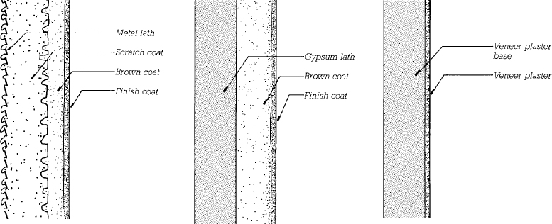
FIGURE 23.13 Sections through the three common lath-and-plaster systems, reproduced at full scale. Metal lath (left) requires three coats of plaster; the surface of the first coat is scratched for a better bond to the second coat. Gypsum lath (middle) may be finished with three coats or with two, as shown. Veneer plaster (right) usually consists of only a single thin finish coat, although two thin coats may be applied over rougher or more uneven substrates, such as concrete masonry or sitecast concrete.

FIGURE 23.14 Scratching the scratch coat while it is still soft to create a better bond to the brown coat. (Courtesy of United States Gypsum Company)
Plaster Over Gypsum Lath The best plaster work over gypsum lath is applied in three coats, but gypsum lath is sufficiently rigid that if it is firmly mounted to the studs, only a brown coat and a finish coat need be applied. The elimination of the scratch coat has obvious economic advantages. Even with three coats of plaster, gypsum lath is often less expensive than metal lath because the gypsum in the lath replaces much of the plaster that would otherwise have to be mixed and applied by hand in the scratch coat. The total thickness of plaster applied over gypsum lath is ½ inch (13 mm).
Plaster Applied to Masonry Where plaster is applied directly over brick, concrete masonry, or poured concrete walls, the walls should be dampened thoroughly in advance of plastering to prevent premature dehydration of the plaster. A bonding agent may have to be applied to some types of smooth masonry surfaces to ensure good adhesion of the plaster. The number of coats of plaster required to cover a wall is determined by the degree of unevenness of the masonry surface. For the best work, three coats totaling ⅝ inch (16 mm) should be applied, but for many walls two coats will suffice (Figure 23.17).
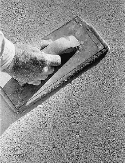
FIGURE 23.15 A sponge-faced float can be used to create various rough surface textures on plaster. (Reprinted with permission of the Portland Cement Association from Design and Control of Concrete Mixtures, 12th edition; Photos: Portland Cement Association, Skokie, IL)

FIGURE 23.16 Three different plaster surface textures from among many. (a) Float finish. (b) Spray finish. (c) Texture finish. (Courtesy of United States Gypsum Company)
Veneer Plaster Veneer plaster is the least expensive of the gypsum plaster systems and is competitive in price with gypsum board finishes in many regions. The veneer base and accessories create a very flat surface that can be finished with a layer of a specially formulated dense gypsum plaster (manufactured to a separate standard, ASTM C587) that is applied in one or, occasionally, two coats usually no more than ![]() to ⅛ inch (2–3 mm) in total thickness (Figures 23.18–23.21). A typical single-coat application is applied in a “double-back” process in which a thin coat is followed immediately by a second “skim” coat that is finish troweled to the desired texture. The plaster veneer hardens and dries so rapidly that it may be painted the following day. A two-coat application of veneer plaster can also be directly applied to surface of sitecast concrete or concrete masonry walls.
to ⅛ inch (2–3 mm) in total thickness (Figures 23.18–23.21). A typical single-coat application is applied in a “double-back” process in which a thin coat is followed immediately by a second “skim” coat that is finish troweled to the desired texture. The plaster veneer hardens and dries so rapidly that it may be painted the following day. A two-coat application of veneer plaster can also be directly applied to surface of sitecast concrete or concrete masonry walls.
Stucco Stucco is applied over galvanized metal lath, using accessories of galvanized steel, or in wet areas or exterior applications, of solid zinc or plastic, which are less prone to corrosion than galvanized steel. Whereas gypsum plaster expands during hardening and is therefore highly resistant to cracking, portland cement stucco shrinks and is prone to cracking. Stucco walls should be provided with control joints at frequent intervals to channel the shrinkage into predetermined lines rather than allowing it to cause random cracks. The curing reaction in stucco is the same as that of concrete and is very slow relative to that of gypsum plaster. Stucco must be kept moist for at least a week before it is allowed to dry in order to attain maximum hardness and strength through full hydration of its portland cement binder.

FIGURE 23.17 Applying a finish coat of portland cement plaster over a concrete masonry partition. The block joints are visible in the base coat of plaster because of a difference in the rate of water absorption between the blocks and the mortar joints. (Reprinted with permission of the Portland Cement Association from Design and Control of Concrete Mixtures, 12th edition; Photos: Portland Cement Association, Skokie, IL)
In exterior applications over metal or wood studs, stucco may be applied over sheathing or without sheathing. Over sheathing, one or preferably two layers of asphalt-saturated building felt or building paper are first applied as an air and moisture barrier. Then a self-furring metal lath, which is formed with “dimples” that hold the lath away from the surface of the wall a fraction of an inch to allow the stucco to key to the lath, is attached with nails or screws (Figure 23.10b). If no sheathing is used, the wall is laced tightly with strands of line wire a few inches apart and paperbacked metal lath is attached to the line wire, after which stucco is applied to encase the building in a thin layer of what amounts to reinforced concrete.
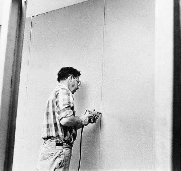
FIGURE 23.18 Installing veneer plaster base with a screw gun. (Courtesy of United States Gypsum Company)
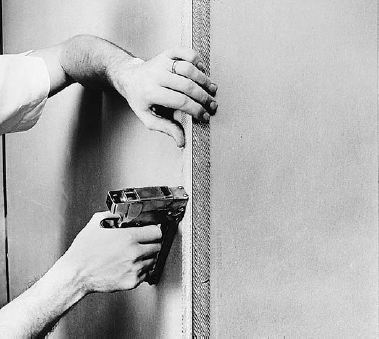
FIGURE 23.19 Stapling a corner bead to veneer plaster base to create a straight, durable corner. (Courtesy of United States Gypsum Company)
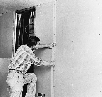
FIGURE 23.20 Reinforcing the panel joints of veneer plaster base with a self-adhesive glass fiber mesh tape. A panel opening for access to mechanical equipment is visible behind the installer. (Courtesy of United States Gypsum Company)
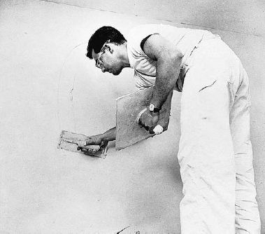
FIGURE 23.21 Applying veneer plaster with a hawk and trowel. (Courtesy of United States Gypsum Company)
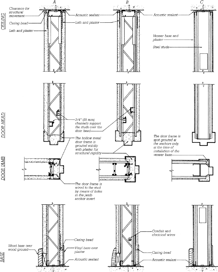
FIGURE 23.22 Three traditional plaster partition systems. (a) Three coats of plaster on metal lath and open-truss wire studs, rated at 1 hour of fire resistance and STC 39. (b) Two coats of plaster over gypsum lath and open-truss wire studs, rated at 1 hour and STC 41. (c) Veneer plaster on light gauge steel studs, rated at 1 hour and STC 40. Notice especially the provisions for airtightness and structural movement at the top and bottom of each partition and the methods of attachment used for hollow metal door frames. Doors weighing more than 50 pounds (23 kg) require special reinforcing details around the frames. In contemporary construction, conventional C-shaped light gauge steel studs are substituted for the open-truss wire studs shown in (a) and (b).

FIGURE 23.23 Two traditional plaster partition systems. (a) This partition increases its STC to 51 by mounting the gypsum lath on one side with resilient metal clips and filling the hollow space in the partition with a sound attenuation blanket. (b) The solid plaster partition has an STC of only 38 but is used in situations where floor space must be conserved. Both of these partitions are rated at 1 hour. In contemporary construction, conventional C-shaped light gauge steel studs are substituted for the open-truss wire studs shown in (a).
In exterior applications, where stucco is exposed to wind-driven rain, it may be applied over a thin, tangled filament matting or vertical furring strips to create a space behind the stucco that improves drainage and reduces the risk of water penetration further into the wall assembly.
Stucco is usually applied in three coats over metal lath, with a total thickness of ⅞ inch (22 mm), or in two coats when applied directly to the surface of concrete or concrete masonry, with a thickness of ⅜ to ½ inch (10–13 mm). It is applied either with a hawk and trowel or by spraying (Figure 6.31). In exterior work, pigments or dyes are often added to stucco to give an integral color, and rough textures are frequently used.
Plaster Partition Systems
Several types of plaster partitions are detailed in Figures 23.22 and 23.23. These diagrams show some of the ways in which the various trim accessories are used and the precautions taken to isolate the partitions from structural or thermal movements in the loadbearing frame of the building.
Gypsum plaster, with its fine grain and even texture, has more sculptural potential than any other material used in architecture. While wet, it is easily formed with trowels and spatulas, molds, or templates. When dry, it is readily worked by sawing, sanding, machining, and carving. Plaster building ornament has been created for many centuries by two economical but powerful techniques, casting and running, and continues to be used in buildings of every size and every historic style.
Cast plaster ornament is made by pouring soupy plaster into molds. The plaster hardens in a few minutes, allowing the mold to be stripped and reused. Both rigid molds and soft rubber molds are used. The rubber molds are very flexible, so even undercut shapes can be cast without encountering difficulties in mold removal. Traditional rubber molds are created by first carving a plaster original, then brushing layers of latex over the original to build up the required wall thickness. More recently, two-component synthetic rubber compounds have replaced latex in most applications; their advantage is that they can be spread over the original in a single application rather than in layers.
Cast ornament is adhered to the brown coat of plaster in walls and ceilings with gobs of wet plaster or a mixture of plaster and glue. Once the ornament has been securely fastened in place, the finish coat of plaster is applied around it, and the plaster surfaces and adjacent pieces of ornament are merged by skillful trowel work and sanding to create a single-piece finish.
Running is used to make linear ornaments (run plaster ornament) such as classic cornice moldings. A rigid blade made of sheet metal or sheet plastic is cut to the profile of the molding. The blade is attached to a sliding wooden frame to create a template. The template is pushed back and forth along a guide strip mounted temporarily on the wall or ceiling while a mixture of lime putty and gauging plaster is inserted in front of the blade, which strikes it off to the desired profile. Repeated passes of the template are required to finish the molding smoothly and perfectly. These passes must be completed before the plaster begins to harden, or the setting expansion of the gypsum will cause the template to bind and spoil the plaster surface. The template may also be attached to a radius guide to produce circular moldings.
Casting and running are often used to reproduce plaster ornament during restoration of historic buildings. Rubber molds for casting can be made directly from existing ornaments, and templates for running duplicates of existing profiles are easily and cheaply produced.
New designs for plaster ornament are readily translated from the architect’s paper sketches into carved plaster originals, from which rubber molds are made and duplicates cast. New profiles for moldings are quickly converted into template blades. The possibilities are almost limitless, yet few contemporary architects have chosen to explore them. This is surprising because plaster ornament is inexpensive compared to ornament carved from wood or stone, and there are few technical constraints on what can be accomplished.
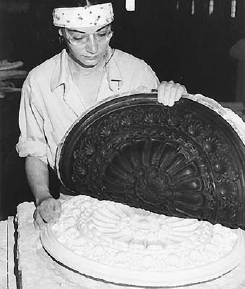
FIGURE A Removing the flexible rubber mold from a cast plaster ornament. (Courtesy of Dovetail, Inc.)

FIGURE B Running a plaster cornice molding in place. (Courtesy of Dovetail, Inc.)
Cast plaster ornament can be reinforced with short fibers of alkali-resistant glass. These greatly increase its strength and toughness and allow it to be produced in much thinner sections and much larger pieces than unreinforced plaster. This recent development has dramatically changed the economics and methods of ornamentation in plaster that is based on stock designs. A number of manufacturers issue catalogs of stock designs for ornaments made by this process. Much of the on-site assembly work for elaborate ornaments can be eliminated by combining what were formerly a number of small, thick, brittle castings into a single, larger, thinner casting that is light in weight and highly resistant to breakage. On the construction site, the lightweight castings are glued in place over gypsum board or veneer plaster base, using an ordinary mastic adhesive. The edges of the ornaments are feathered into the wall or ceiling surfaces with joint compound or veneer plaster, and the joints between pieces of ornament are smoothed over and sanded.
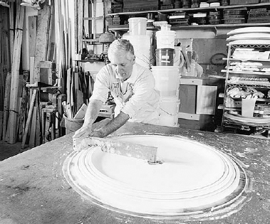
FIGURE C Sculptor David Flaharty runs a circular plaster medallion on a bench in his shop. (© Brian McNeill)

FIGURE D A close-up of Flaharty’s blade and template. The template rides on the sledlike runner of the portion under his hand, which is called the “slipper.” The long portion of the template, called the “stock,” is a radius guide that is fastened to a pin at the end to create the circular form of the medallion. (© Brian McNeill)
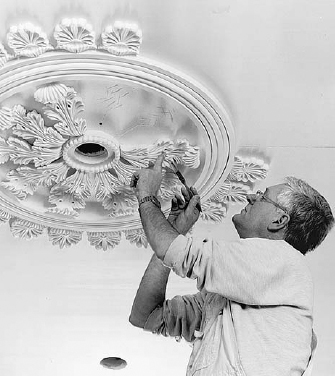
FIGURE E The medallion having been removed from the bench and glued in place on the ceiling, Flaharty adds cast components to complete the ornament. (© Brian McNeill)
Gypsum Board
Gypsum board is a prefabricated plaster sheet material that is manufactured in widths of 4 feet(1220 mm) and lengths of 8 to 14 feet (2440–4270 mm). It is also known as gypsum wallboard, plasterboard, and drywall. (The term “sheetrock” is a registered trademark of one manufacturer of gypsum board and should not be used in a generic sense.)
Gypsum board is the least expensive of all interior finishing materials for walls and ceilings. For this reason alone, it has found wide acceptance throughout North America as a substitute for plaster in buildings of every type. It retains the fire-resistive characteristics of gypsum plaster, but it is installed with less labor by less skilled workers than lathers and plasterers. And because it is installed largely in the form of dry materials, it eliminates some of the construction delay that may be associated with the curing and drying of plaster.
The core of gypsum board is formulated as a slurry of calcined gypsum, starch, water, pregenerated foam to reduce the density of the mixture, and various additives. This slurry is sandwiched between special paper faces and passed between sets of rollers to reduce it to the desired thickness. Within 2 or 3 minutes, the core material has hardened and bonded to the paper faces. The board is cut to length and heated to drive off residual moisture, then bundled for shipping (Figure 23.24).
Types of Gypsum Board
Gypsum board is produced in a variety of types suitable to a wide range of requirements:
• Regular gypsum board is used wherever the unique properties of other special board types are not required.

FIGURE 23.24 Sheets of gypsum board roll off the manufacturing line, trimmed and ready for packaging. (Courtesy of United States Gypsum Company)
• For most types of fire-rated assemblies, Type X gypsum board is required. The core material of Type X board is reinforced with short glass fibers. In a severe fire, the fibers hold the calcined gypsum in place to continue to act as a barrier to fire rather than permitting it to erode or fall out.
• Type C gypsum board is a proprietary formulation that is more fire resistant than Type X. Often a thinner board of Type C may generally be substituted for a thicker one of Type X.
• In locations exposed to moderate amounts of moisture, water-resistant gypsum backing board, with facings of water-repellant paper or glass matt, and a moisture-resistant core formulation is used.
• Abuse-resistant or impact-resistant gypsum board provides greater resistance to indentation and penetration and is intended for use in buildings that are exposed to rough usage. It may be manufactured with heavier facing paper and backing sheets, may have its core reinforced with cellulose fibers, may be faced with glass fiber mesh, or may be backed with polycarbonate film.
• Mold-resistant gypsum board is manufactured to resist moisture and mold growth. The common paper facing on gypsum board can, when wetted, provide conditions suitable to the growth of mold spores. Mold-resistant boards combine moisture-resistant cores with chemically treated paper facings or glass-matt facings that are not conducive to mold growth. At least one panel product is manufactured with a gypsum core blended with cellulose fibers that greatly strengthen the board and eliminate the need for facing materials of any kind.
• Coreboard is a 1-inch (25.4-mm)-thick panel that is used for shaft walls and solid gypsum board partitions. To facilitate handling, it is fabricated in sheets 24 inches (610 mm) wide.
• Sag-resistant ceiling gypsum board, ½ inch (13 mm) thick, is substantially lighter than, but just as resistant to sagging when used in ceiling assemblies as ⅝-inch (15-mm) panels.
• Foil-backed gypsum board can be used to eliminate the need for a separate vapor retarder in outside wall assemblies. If the back of the board faces a dead airspace at least ¾ inch (19 mm) thick, the bright foil also acts as a thermal insulator.
• Predecorated gypsum board is board that has been covered with paint, printed paper, or decorative plastic film. If handled carefully and installed with small nails, it needs no further finishing. This product is used in a number of demountable office partitioning systems.
• Weather-resistant exterior gypsum soffit board is used for exterior soffits, carport ceilings, undersides of exterior canopies, and other sheltered exterior applications.
• Gypsum lath and gypsum veneer base, as previously discussed.
Most gypsum board product types are manufactured in conformance with ASTM standard C1396. (Some related products, such as fiber cement backing board or glass matt–faced gypsum board, are manufactured to separate standards.)
Gypsum board is manufactured with a variety of edge profiles along its longer sides. The most common by far is the tapered edge, which permits sheets to be joined with a flush, invisible seam by means of subsequent joint finishing operations. Rounded and beveled edges are useful in predecorated panels, and tongue-and-groove edges serve to join coreboard panels in concealed locations. The edges of the shorter ends of gypsum board panels are not tapered or shaped, since the individual panels are cut from longer continuous sheets during manufacturing.

FIGURE 23.25 Attaching gypsum board to studs with a screw gun. (Courtesy of United States Gypsum Company)
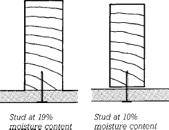
FIGURE 23.26 When wood studs dry and shrink during a building’s first heating season, nail heads may pop through the surface of gypsum board walls.
Many different thicknesses of board are produced:
• ¼-inch (6.4-mm) board is used as a gypsum backing board in certain sound control applications. A special ¼-inch board is also produced by some manufacturers to be used for tight-radius bends (Figure 23.29).
• ![]() -inch (8-mm) board is made for manufactured housing, where weight reduction to facilitate shipping is an important consideration.
-inch (8-mm) board is made for manufactured housing, where weight reduction to facilitate shipping is an important consideration.
• ⅜-inch (9.5-mm) board is largely used in double-layer wall finishes. Though less durable than thicker panels, it may also sometimes be applied as a single-layer finish over ceiling joists or wall studs spaced no more than 16 inches (400 mm) apart.
• ½-inch (12.7-mm) board is the most common thickness. It is used for stud and joist spacings up to 24 inches (610 mm).
• ⅝-inch (16-mm) board is also limited to stud spacings of not more than 24 inches (610 mm), but it is often used where additional fire resistance, structural stiffness, durability, or sound deadening is required.
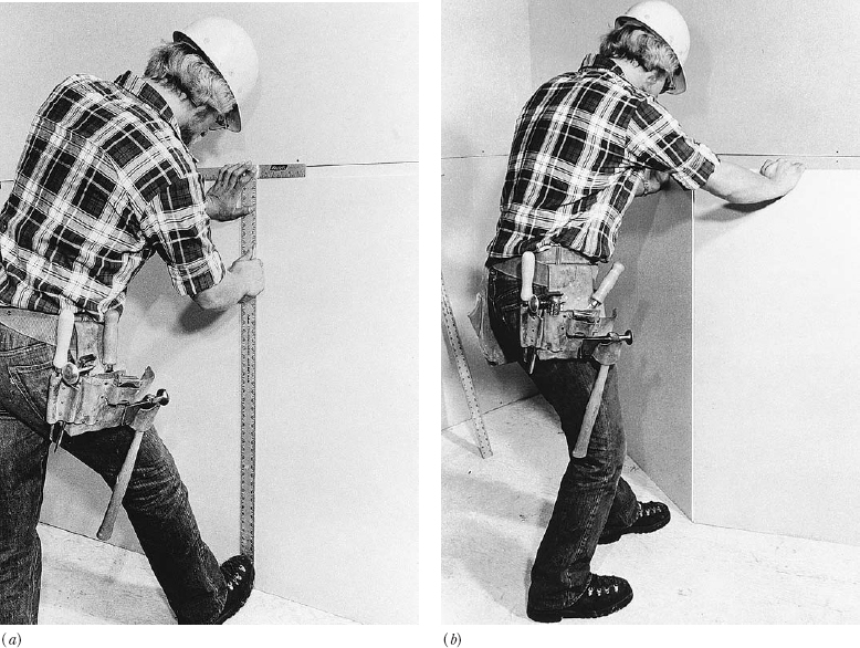
FIGURE 23.27 Cutting gypsum board. (a) A sharp knife and metal T-square are used to score a straight line through one paper face of the panel. (b) The scored board is easily “snapped,” and the knife is used a second time to slit the second paper face. (Courtesy of United States Gypsum Company)
• ¾-inch (19-mm) Type X board is produced by some manufacturers. It is used to create 2-hour partitions with a single layer of gypsum board on each face and 4-hour partitions that include two layers on each face.
• 1-inch (25.4-mm)-thick board is made only as coreboard for use, for example, in shaft wall construction (Figure 23.38).
Installing Gypsum Board
Hanging the Board Gypsum board may be installed over either wood or light gauge steel studs, using self-drilling, self-tapping screws to fasten to steel and either screws or nails to fasten to wood (Figure 23.25). Wood studs can be troublesome with gypsum board because they usually shrink somewhat after the board is installed, which can cause nails to loosen slightly and “pop” through the finished surface of the board (Figure 23.26). Nail popping can be minimized by using only fully dried framing lumber, by using ring-shank nails that have extra gripping power in the wood, and by using the shortest nail that will do the job. Screws have less tendency to pop than nails. When screws or nails are driven into gypsum board, their heads are driven to a level slightly below the surface of the board but not enough to tear the paper surface.

FIGURE 23.28 Gypsum board can be curved to a large radius by simply bending it around a curving line of studs. (Courtesy of United States Gypsum Company)
To minimize the length of joints that must be finished and to create the stiffest wall possible, gypsum board is usually installed with the long dimension of the boards horizontal. The longest possible boards are used to eliminate or at least minimize end joints between boards, which are difficult to finish because the ends of boards are not tapered. Gypsum board is cut rapidly and easily by scoring one paper face with a sharp knife, snapping the brittle core along the score line with a blow from the heel of the hand, and cutting the other paper face along the fold created by the snapped core (Figure 23.27). A special metal T-square is used to make straight cuts that are perpendicular to the edges of the board. Notches, irregular cuts, and holes for electric boxes are made with a small saw or small electric router.
When two or more layers of gypsum board are installed on a surface, the joints between layers are staggered to create a stiffer wall, and a mastic adhesive is often used to join the layers to one another. Adhesive is also sometimes used between the studs and the gypsum board in single-layer installations to make a stronger joint.
Gypsum board can be curved when a design requires it. For gentle curves, the board can be bent into place dry (Figure 23.28). For somewhat sharper curves, the paper faces are moistened to decrease the stiffness of the board before it is installed. When the paper dries, the board is as stiff as before. Special high-flex ¼-inch (6.5-mm) board is available that can be bent dry to a relatively small radius and bent wet to an even smaller radius (Figure 23.29).
Metal trim accessories are required at exposed edges and external corners to protect the brittle board and present a neat edge (Figure 23.30). These are similar to lathing accessories for plaster.
Finishing the Joints and Fastener Holes Joints and holes in gypsum board are finished to create the appearance of a monolithic surface almost indistinguishable from plaster. The finishing process is based on the use of a joint compound that resembles a smooth, sticky plaster. For most purposes, a drying-type joint compound is used; this is a mixture of marble dust, binder, and admixtures, furnished either as a dry powder to be mixed with water or as a premixed paste. In some high-production commercial work, setting compounds that cure rapidly by chemical reaction are used to minimize the waiting time between applications. Joint compounds of different weights and strengths may be used for different stages of the joint finishing process, or a single all-purpose compound may be used for all steps.

FIGURE 23.29 Tighter radii of curvature can be achieved by using ¼-inch (6.5-mm) high-flex gypsum board. (Photo courtesy of National Gypsum Company)
The finishing of a joint between panels of gypsum board begins with the troweling of a layer of joint compound into the tapered edge joint and the bedding of a paper or glass fiber reinforcing tape in the compound (Figures 23.31–23.34). Compound is also troweled over the nail or screw holes. After drying (usually overnight), a second layer of compound is applied to the joint to bring it level with the face of the board and to fill the space left by the slight drying shrinkage of the joint compound. When this second coat is dry, the joints are lightly sanded before a very thin final coat is applied to fill any remaining voids. The final coat is featured out (tapered down to zero thickness) to create an invisible edge. Before painting, the wall is again sanded lightly to remove any roughness or ridges. If the finishing is done properly, the painted or papered wall will show no signs at all that it is made of discrete panels of material.
Gypsum board has a smooth surface finish, but a number of spray-on textures and textured paints can be applied to give a rougher surface. Most gypsum board contractors prefer to texture ceilings; the texture conceals the minor irregularities in workmanship that are likely to occur because of the difficulty of working in the overhead position.
FIGURE 23.30 Accessories for gypsum board construction, as manufactured by the United States Gypsum Company. (Courtesy of United States Gypsum Company)
Standardized gypsum board finish levels have been developed by the Gypsum Association and are also specified in ASTM C840. These enable the designer to specify quickly and simply the minimum level of finish that is acceptable for any project or portion of a project.
• Level 0, the minimum, consists of just the boards, without taping, finishing, or accessories. It is usually used only for temporary construction or where finishing is postponed until a later date.
• Level 1 requires only that joints be covered with tape set in joint compound. Its primary use is in areas of the building that are not open to view, such as above ceilings, in attics, and in service corridors. Level 1 is also the minimum finish level for fire-resistance-rated gypsum board assemblies, in which applications it may also be referred to as fire-taping.
• Level 2 adds to a Level 1 finish a coat of joint compound over the accessories and fasteners. After joint tape is set in compound, these joints are also immediately wiped with a joint knife a second time to add a thin coat of compound over the tape. A Level 2 finish is appropriate in garages, warehouses, and storage areas, and for boards used as a backer for ceramic tile.
• Level 3 adds a full second coat of compound over tape, accessories, and fasteners after the first coat has dried. It is intended for surfaces that will be textured or covered with heavy wallcoverings.

FIGURE 23.31 Finishing a joint between panels of gypsum board.
FIGURE 23.32 Applying paper joint reinforcing tape to gypsum board. (Courtesy of United States Gypsum Company).

FIGURE 23.33 An automatic taper simultaneously applies tape and joint compound to gypsum board joints. (Courtesy of United States Gypsum Company)

• Level 4 is designed for surfaces to be finished with flat paints, light textures, or thin wallcoverings. It adds a third distinct coat of joint compound over taped seams, fasteners, and accessories.
• Level 5, the highest, adds a very thin skim coat of joint compound over the entire surface of the board. The skim coat has no measurable thickness, because its purpose is only to fill pores and low spots in the wall to produce a very smooth surface. It is recommended for surfaces that will receive gloss or semigloss paints and for surfaces that will be lit in such a way as to cast shadows that can highlight even slight imperfections.

FIGURE 23.34 Plasterers and drywall finishers often work on stilts to avoid having to erect and move scaffolding. The stilts, which are strapped to the legs of the workers, are very sophisticated, stable devices that keep the worker’s foot fully supported and parallel to the floor. (Photo by Rob Thallon)
Gypsum Board Partition Systems
Gypsum board partition assemblies have been designed and tested with fire resistance ratings of up to 4 hours and sound transmission performance of up to at least STC 69. A selection of such partitions is shown in Figure 23.35. Notice in these details how provisions are made to prevent the gypsum panels from being subjected to structural loadings caused by movements in the loadbearing frame of the building—structural deflections, concrete creep, moisture expansion, and temperature expansion and contraction. Notice also the use of sealant to eliminate sound transmission around the edges of the partitions.
Demountable partition systems of gypsum board have also been developed, using concealed mechanical fasteners that can be disassembled and reassembled easily without damage to the panels (Figure 23.37). These systems are used in buildings whose partitions must be rearranged at frequent intervals.
FIGURE 23.35 Four gypsum board partition systems. (a) A 1-hour partition, STC 40, using Type X gypsum board over light gauge steel studs. (b) This 1-hour partition on wood studs achieves an STC of 60 to 64 through heavy laminations of gypsum board, a sound attenuation blanket, and resilient channel mounting for one face of the partition. (c) A 2-hour partition with an STC of 48. (d) A 4-hour partition, STC 58. These are representative of a large number of gypsum board partition systems in a range of fire ratings and sound transmission classes.


FIGURE 23.36 Installing a sound attenuation blanket. (Courtesy of United States Gypsum Company)
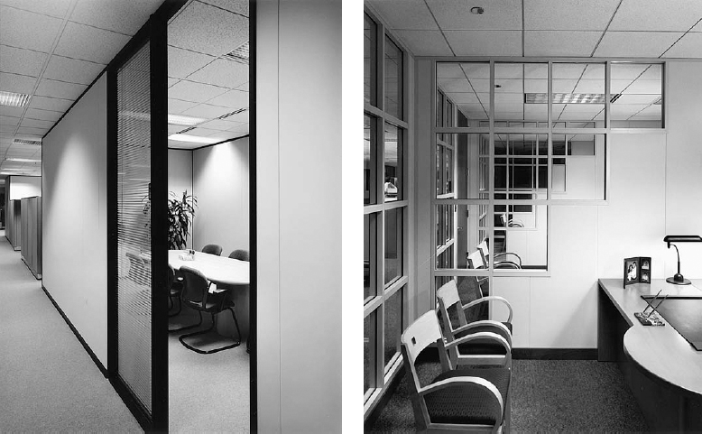
FIGURE 23.37 Two photographs of relocatable (demountable) partition systems. (Courtesy of United States Gypsum Company)
Gypsum Shaft Wall Systems
Walls around elevator shafts, stairways, and mechanical chases can be made of any masonry, lath and plaster, or gypsum panel assembly that meets fire resistance and structural requirements. Gypsum shaft wall systems offer several advantages over the alternatives: They are lighter in weight, they are installed dry, and they are built entirely from the floor outside the shaft, with no need to erect scaffolding inside. Depending on the requirements for fire resistance rating, air pressure resistance, STC, and floor-to-ceiling height, any of several designs may be used. Figure 23.38 shows representative shaft wall details, and Figure 22.1 shows a shaft wall being installed.
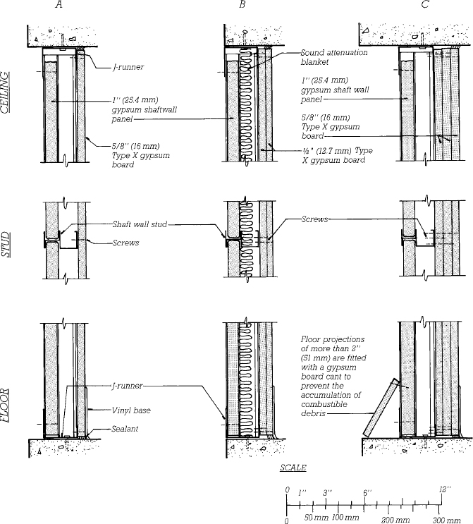
FIGURE 23.38 Three gypsum shaft wall systems, all framed with steel C–H studs. The H portion of the stud holds a 1-inch (25-mm) shaft wall coreboard panel, while the C portion accepts the screws used to attach finish layers of gypsum board. (a) A 1-hour system. (b) A 2-hour system, STC 47. (c) A 3-hour system.
Leave a Reply