Pouring (casting) of the slab commences with placing concrete in the formwork. This may be done directly from the chute of a transit-mix truck, or with wheelbarrows, concrete buggies, a large crane-mounted concrete bucket, a conveyor belt, or a concrete pump and hoses. The method selected will depend on the scale of the job and the accessibility of the slab to the truck delivering the concrete. The concrete is spread by workers using shovels or rakes until the form is full. Then the same tools are used to agitate the concrete slightly, especially around the edges, to eliminate air pockets. As the concrete is placed, the concrete masons reach into the wet concrete with metal hooks and raise the welded wire fabric to approximately the midheight of the slab, the position in which it is best able to resist tensile forces caused by forces acting either upward or downward on the slab.
The first operation in finishing the slab is to strike off or screed the concrete by drawing a stiff plank of wood or metal across the top edges of the formwork to achieve a level concrete surface (Figure 14.3d). This is done with an end-to-end sawing motion of the plank that avoids tearing the projecting pieces of coarse aggregate from the surface of the wet concrete. A bulge of concrete is maintained in front of the screed as it progresses across the slab, so that when a low point is encountered, concrete from the bulge will flow in to fill it.
Immediately after striking off the concrete, the slab receives its initial floating. This step is usually performed by hand, using flat-surfaced tools, typically 4 to 10 feet (1.2 to 3 m) in length, called bull floats or darbies (Figure 14.3e). These are drawn across the concrete to flatten and consolidate its surface. After this initial floating, the top of the slab is level but still rather rough. If a concrete topping will later be poured over the slab, or if a floor finish of terrazzo, stone, brick, or quarry tile will be applied, the slab may be left to cure without further finishing.
If a smoother surface is desired, additional finishing operations proceed after a period of time during which the concrete begins to stiffen and the watery sheen, called bleed water, evaporates from the surface of the slab. First, specially shaped hand tools may be used to form neatly rounded edges around the perimeter of the slab and control joints in the interior. Next, the slab is floated a second time to further consolidate its surface. At this stage, small slabs may be floated by hand (Figure 14.3f), but for larger slabs, rotary power floats are used (Figure 14.3g). The working surfaces of floats are made of wood or of metal with a slightly rough surface. As the float is drawn across the surface, the friction generated by this roughness vibrates the concrete gently and brings cement paste to the surface, where it is smoothed over the coarse aggregate and into low spots by the float. If too much floating is done, however, an excess of paste and free water rises to the surface and forms puddles, making it almost impossible to get a good finish. Experience on the part of the mason is essential to floating, as it is to all slab finishing operations, to know just when to begin each operation and just when to stop. The floated slab has a lightly textured surface that is appropriate for outdoor walks and pavings without further finishing.
For a completely smooth, dense surface, the slab must also be troweled. This is done immediately after the second floating, either by hand, using a smooth, rectangular steel trowel (Figure 14.3h), or with a rotary power trowel. If the concrete mason cannot reach all areas of the slab from around the edges, squares of plywood called knee boards, two per mason, are placed on the surface of the concrete. These distribute the mason’s weight sufficiently that he or she can kneel on the surface without making indentations. Any marks left by the knee boards are removed by the trowel as the mason works backward across the surface from one edge to the other. If a nonslip surface is required, a stiff-bristled janitor’s pushbroom is drawn across the surface of the slab after troweling to produce a striated texture called a broom finish.
Where a concrete slab must meet narrow floor flatness limits, it may be restraightened after each floating or troweling operation. Restraightening is commonly performed with a rectangular flat-bottomed straightedge, roughly 10 feet (3 m) in length, which is drawn across the concrete slab surface to remove minor undulations produced during floating or troweling.
Shake-on hardeners are sometimes sprinkled over the surface of a slab between the screeding and floating operations. These dry powders react with the concrete to form a very hard, durable surface for such heavy-wear applications as warehouses and factories.
When the finishing operations have been completed, the slab should be cured under damp conditions for at least a week; otherwise, its surface may crack or become dusty from premature drying. Damp curing may be accomplished by covering the slab with an absorbent material such as sawdust, earth, sand, straw, or burlap and maintaining the material in a damp condition for the required length of time. Or an impervious sheet of plastic or waterproof paper may be placed over the slab soon after troweling to prevent the escape of moisture from the concrete (Figure 14.3j). The same effect may be obtained by spraying the concrete surface with one or more applications of a liquid curing compound, which forms an invisible moisture barrier membrane over the slab.
No concrete floor is perfectly flat. The normal finishing process produces a surface that undulates, usually imperceptibly, between low and high areas that go unnoticed in everyday use. Traditionally, the flatness of concrete slabs is specified as the maximum gap size, typically in the range of ⅛ to ⅜ inch (3 to 10 mm), permitted under a 10-foot (3-m) straightedge placed anywhere on the floor. Industrial warehouses that use high-rise forklift trucks, however, require floors whose flatness is controlled to within more narrow tolerances. These superflat floors, as well as other floors where close control over flatness is desired, are specified according to a more complicated system of index numbers, called F-numbers, that correspond to the degrees of flatness (waviness) and levelness (conformity to a horizontal plane) that are required, and are produced using special finishing equipment and techniques. Because of its extreme accuracy, a laser-guided automatic straightedging machine (Figure 14.4) is often used in the creation of superflat floors. This device produces a slab surface that is flat and level to within consistently small tolerances, and does so at a very rapid rate.
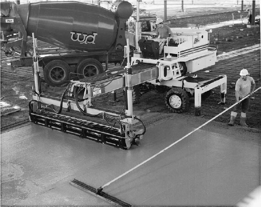
FIGURE 14.4 Guided by a laser beam, the motorized straightedging device on this machine can strike off 240 square feet (22 m2) of slab surface per minute to an extremely exacting standard of flatness. The worker to the right smooths the surface with a bull float. (Photo by Wironen, Inc. Courtesy of the Laser Screed Company, Inc., New Ipswich, New Hampshire)
Controlling Cracking in Concrete Slabs on Grade
Because concrete slabs on grade are relatively thin in relation to their horizontal dimensions and usually are relatively lightly reinforced, they are particularly prone to cracking. The stresses that cause cracking may originate from the shrinkage that is a normal part of the concrete curing process, from thermal expansion and contraction of the slab, or from differential movement between the slab and abutting building elements. If such cracks are allowed to occur randomly, they can be unsightly and can compromise the functionality of the slab.
Most commonly, cracking in concrete slabs on grade is managed by introducing an organized system of joints into the slab that allow stresses to be relieved without compromising the appearance or performance of the slab. Control joints, also called contraction joints, are intentionally weakened sections through a concrete slab where the tensile forces caused by concrete drying shrinkage can be relieved without disfiguring the slab. They are usually formed as grooves that extend at least one-quarter of the depth of the slab, created either by running a special trowel along a straightedge while the concrete is still plastic or by sawing partially through the concrete shortly after it begins to harden using a diamond or abrasive saw blade in a power circular saw. To provide a further inducement for cracks to occur at control joint locations rather than elsewhere in the slab, reinforcing in the slab may be partially discontinued where it crosses these joints. Control joint spacing recommendations vary with the thickness of the slab and the shrinkage rate of the concrete. For example, for slabs 4 to 8 inches (100–200 mm) thick made with ordinary concrete, joints spacings from 11 feet 6 inches to 17 feet 6 inches (3.6–5.3 m) are recommended (the thinner the slab, the closer the joint spacing) Where control joints run in perpendicular directions, they should be spaced more or less equally in each direction to create panels that are square or close to square in proportion.
Reinforced concrete made “pilotis” possible. The house is in the air, away from the ground; the garden runs under the house, and it is also above the house, on the roof. . . . Reinforced concrete is the means which makes it possible to build all of one material. . . . Reinforced concrete brings the free plan into the house! Floors no longer have to stand simply one on top of the other. They are free. . . . Reinforced concrete revolutionizes the history of the window. Windows can run from one end of the facade to the other …
Le Corbusier and P. Jeanneret, Oeuvre Complète 1910–1929, 1956.
Isolation joints, sometimes also called expansion joints, are formed by casting full-depth preformed joint materials, typically ⅜ to ¾ inch (10–20 mm) in width, into the slab (Figure 14.3c), completely separating the slab from adjacent elements. Isolation joints relieve potential stresses by allowing freedom of movement of the slab with respect to other building parts or other portions of the slab—movements that may occur due to thermal expansion and contraction, structural loading, or differential settlement. Isolation joints are commonly provided where the edge of a concrete slab abuts adjacent walls or curbs, as well as around elements, such as columns or loadbearing walls, which pass through the slab within its perimeter. Isolation joints are also used to divide large or irregularly shaped slabs into smaller, more simply shaped rectangular areas that are less prone to stress accumulation.
Concrete itself can be manipulated to reduce cracking: Shrinkage-reducing chemical admixtures and some supplementary cementitious materials, such as fly ash, reduce drying shrinkage. Lowering the water–cement ratio of the concrete mix both reduces drying shrinkage and results in finished concrete that is stronger and more crack resistant. Specially formulated shrinkage-compensating cements can completely nullify drying shrinkage, allowing the casting of large slabs on grade entirely free of contraction joints. The amount of steel reinforcing in the slab can be increased or fibrous reinforcing can be added to the concrete mix to improve a concrete slab’s resistance to tensile forces. Protecting a freshly poured concrete slab from premature drying during the damp curing process reduces cracking while the concrete hardens and ensures that the concrete attains its full design strength.
Under certain circumstances, it is advantageous to posttension a slab on grade, using level tendons in both directions at the midheight of the slab rather than welded wire fabric. Posttensioning places the entire slab under sufficient compressive stress so that it will never experience tensile stress under any anticipated conditions. Posttensioning makes floors resistant to cracking under concentrated loads, eliminates the need to make control joints, and often permits the use of a thinner slab. It is especially effective for slabs over unstable or inconsistent soils and for superflat floors.
Leave a Reply