
One-Way Solid Slab System
A one-way solid slab (Figures 14.16–14.19) spans across parallel lines of support furnished by walls and/or beams. The walls and columns are poured prior to erecting the formwork for a one-way slab, but the forms for the girders and beams are nearly always built continuously with those for the slab, and girders, beams, and slab are poured simultaneously as a single piece.
The girder and beam forms are erected first, then the slab forms. The forms are supported on temporary joists and beams of metal or wood, and the temporary beams are supported on temporary shores (adjustable-length columns). The weight of uncured concrete that must be supported is enormous, and the temporary beams and shoring must be both strong and closely spaced. Formwork is, in fact, designed by a contractor’s structural engineers just as carefully as it would be if it were a permanent building, because a structural failure in formwork is an intolerable risk to workers and property.
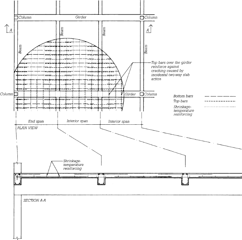
FIGURE 14.16 Plan and larger-scale section of a typical one-way solid slab system. For the sake of clarity, the girder and beam reinforcing are not shown in the plan, and the girder and column reinforcing are left out of the section. The slabs span between the beams, the beams are supported by the girders, and the girders rest on the columns.
Edges of concrete structural elements are beveled or rounded by inserting shaped strips of wood or plastic into the corners of the formwork to produce the desired profile. This is done because sharp edges of concrete often break off during form stripping to leave a ragged edge that is almost impossible to patch. In service, sharp edges are easily damaged by, and are potentially damaging to, people, furniture, and vehicles.
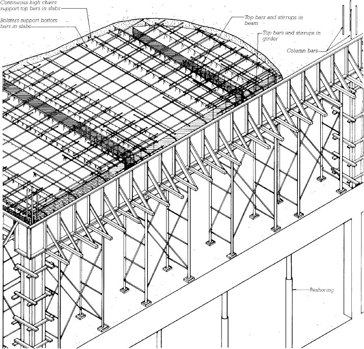
FIGURE 14.17 Isometric view of a one-way solid slab system under construction. The slab, beams, and girders are created in a single pour.
A form release compound is applied to all formwork surfaces that will be in contact with concrete. Then, in accordance with reinforcing diagrams and schedules prepared by the structural engineer, the girder and beam reinforcing— bottom bars, top bars, and stirrups— is installed in the forms, supported on chairs and bolsters to maintain the required cover of concrete. Next, the slab reinforcing—bottom bars, top bars, and shrinkage–temperature bars—is placed on bolsters. After the reinforcing and formwork have been inspected, the girders, beams, and slab are poured in a single operation, with sample cylinders being made for later testing to be sure that the concrete is strong enough. One-way slab depths are typically 4 to 10 inches (100–250 mm), depending on the span and loading intensity. The top of the slab is finished in the same manner as a slab on grade, usually to a steel trowel finish, and the slab is sealed or covered for damp curing. The only components left projecting above the slab surface at this stage are the offset column bars, which are now ready to overlap with, or splice to, the column bars for the floor above.
When the slab and beams have attained enough strength to support themselves safely, the formwork is stripped and the slabs and beams are reshored with vertical props to relieve them of loads until they have reached full strength, which will take several more weeks. Meanwhile, the formwork and the remainder of the shoring are cleaned and moved up a level above the slab and beams just poured, where the cycle of forming, reinforcing, pouring, and stripping is repeated (Figure 14.19).
Ordinarily, the most efficient and economical concrete beam is one whose depth is twice or three times its breadth. One-way solid slabs are often supported, however, by beams that are several times as broad as they are deep. These are called slab bands (Figure 14.20). Banded slab construction offers two kinds of economy: The width of the slab band reduces the span of the slab, which can result in a reduced thickness for the slab and consequent savings of concrete and reinforcing steel. Also, the reduced depth of the slab band compared to a more conventionally proportioned concrete beam allows for reduction of the story height of the building, with attendant economies in columns, cladding, partitions, and vertical runs of piping and ductwork.
FIGURE 14.18 An example of a beam–column connection in a one-way solid slab structure, with the slab reinforcing omitted for clarity. Notice how the column bars are spliced by overlapping them just above floor level. The bars from the column below are offset at the top so that they lie just inside the bars of the column above at the splice. Structural continuity between the beam and column is established by running the top bars from the beam into the column. U-stirrups are shown in the beam; closed stirrup ties, shown in the inset detail, are often used instead.
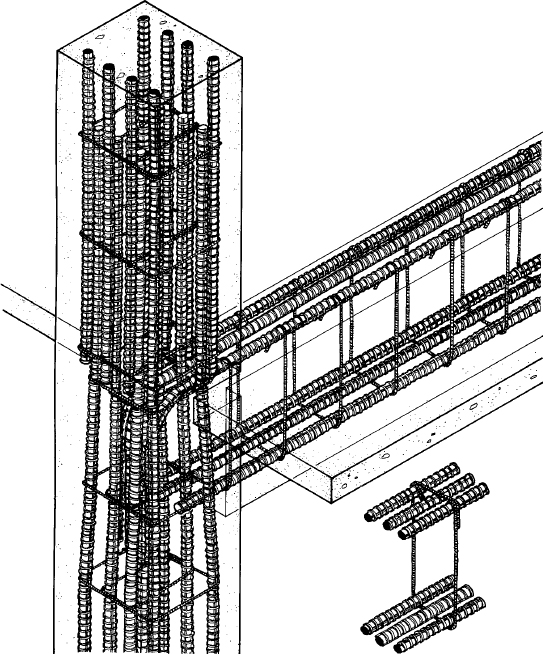

FIGURE 14.19 Reshoring in concrete slab construction. The three uppermost floors visible below the formwork system in this concrete tower have been reshored. The formwork is a climbing system that lifts itself up the structure as each floor is completed. The solid panels surrounding the outside of the formwork protect the work and the workers from the wind and rain. The concrete system is a two-way flat plate, a floor framing system described later in this chapter. (Photo by Joseph Iano)
FIGURE 14.20 Banded slab construction. Compare the depth and breadth of the slab band in the center of the building to those of the conventional concrete beams around the perimeter. (Reprinted with permission of the Portland Cement Association from Design and Control of Concrete Mixtures, 12th edition; Photos: Portland Cement Association, Skokie, IL)
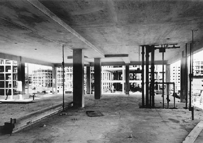
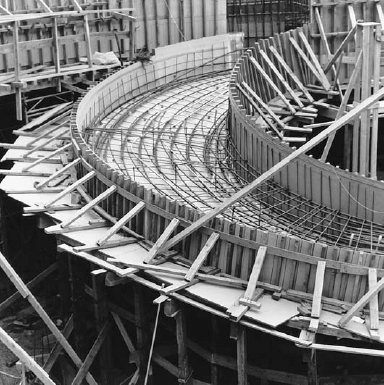
FIGURE 14.21 This helical ramp is a special application of one-way solid slab construction. The formwork is made of overlaid plywood for a smooth surface finish. (Courtesy of APA–The Engineered Wood Association)
One-Way Concrete Joist System (Ribbed Slab)
As one-way solid slab spans increase, a progressively thicker slab is required. Beyond a certain span, the slab becomes so thick that the weight of the slab itself is an excessive burden, unless a substantial portion of the nonworking concrete in the lower part of the slab can be eliminated to lighten the load. This is the rationale for the one-way concrete joist system (Figures 14.22–14.25), also called a ribbed slab. The bottom steel is concentrated in spaced ribs or joists. The thin slab that spans across the top of the joists is reinforced only by shrinkage–temperature bars. There is little concrete in this system that is not working, with the result that a one-way concrete joist system can efficiently and economically span considerably longer distances than a one-way solid slab. Each joist is reinforced as a small beam, except that stirrups are not usually used in concrete joists because of the restricted space in the narrow joist. Instead, the ends of the joists are broadened sufficiently that the concrete itself can resist the diagonal tension forces.
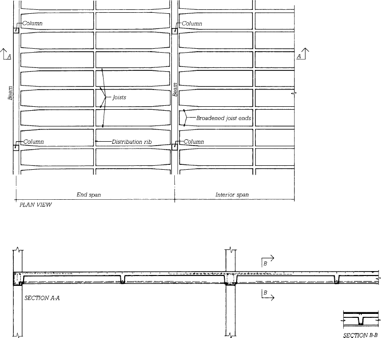
FIGURE 14.22 Plan and larger-scale section of a typical one-way concrete joist system. For the sake of clarity, no reinforcing is shown in the plan, and the column reinforcing is not shown on the section. All bottom and top reinforcing occurs in the ribs, and all shrinkage–temperature bars are placed in the slab.
FIGURE 14.23 Standard steel form dimensions for one-way concrete joist construction. (One inch equals 25.4 mm.) (Courtesy of the Ceco Corporation, Oakbrook Terrace, Illinois)
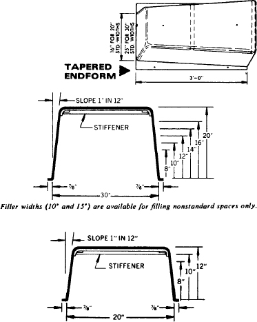
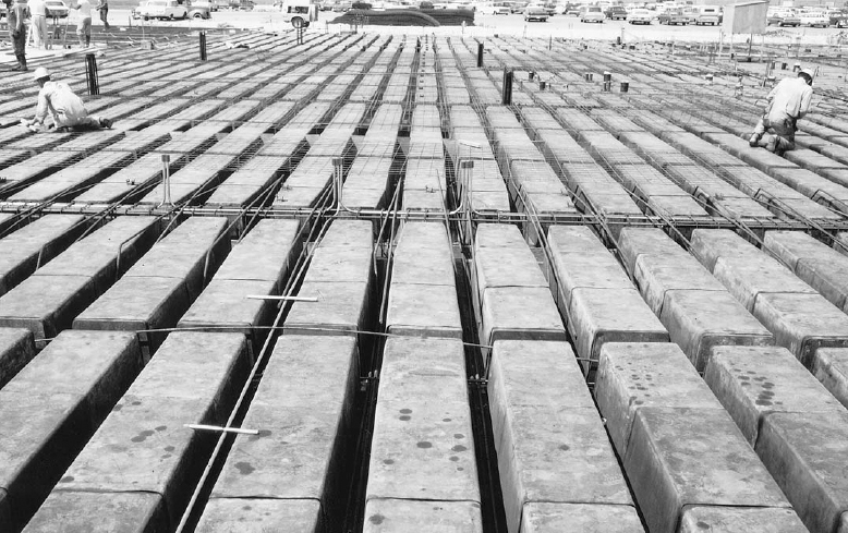
FIGURE 14.24 Reinforcing being placed for a one-way concrete joist floor. Electrical conduits and boxes have been put in place, and welded wire fabric is being installed as shrinkage–temperature reinforcing. Both the tapered end pans and the square endcaps for the midspan distribution rib are clearly visible. (Courtesy of the Ceco Corporation, Oakbrook Terrace, Illinois)
The joists are formed with metal or plastic pans supported on a temporary plywood deck. Pans are available in two standard widths, 20 inches (508 mm) and 30 inches (762 mm), and in depths ranging up to 20 inches (508 mm), as shown in Figure 14.23. (Larger pans are also available for forming floors designed as one-way solid slab systems.) The sides of the pans taper from bottom to top to allow them to drop easily from the hardened concrete during stripping. The joist width can be varied by placing the rows of pans closer together or farther apart. The bottom of each joist is formed by the wood deck. The joist ends are broadened with standard end pans whose width tapers. A distribution rib is sometimes formed across the joists at midspan to distribute concentrated loads to more than one joist. After application of a form release compound, the beam and joist reinforcing are placed, the shrinkage–temperature bars are laid crosswise on bolsters over the pans, and the entire system is poured and finished (Figures 14.24 and 14.25).
One-way concrete joists are usually supported on joist bands, which are broad beams that are only as deep as the joists. Although a deeper beam would be more efficient structurally, a joist band is formed by the same plywood deck that supports the pans, which eliminates expensive beam formwork entirely and produces a simpler underside of slab profile with a uniform floor-to-ceiling height throughout.
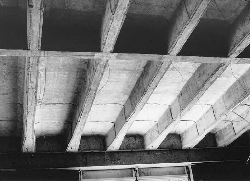
FIGURE 14.25 A one-way concrete joist system after stripping of the formwork, showing broadened joist ends at the lower edge of the photograph and a distribution rib in the foreground. The dangling wires are hangers for a suspended finish ceiling (see Chapter 24). (Reprinted with permission of the Portland Cement Association from Design and Control of Concrete Mixtures, 12th edition; Photos: Portland Cement Association, Skokie, IL)
Wide-Module Concrete Joist System
When fire-resistance requirements of the building code dictate a slab thickness of 4½ inches (115 mm) or more, the slab is capable of spanning a much greater distance than the normal space between joists in a one-way concrete joist system. This has led to the development of the wide-module concrete joist system, also called the skip-joist system, in which the joists are placed 4 to 6 feet (1220–1830 mm) apart. The name “skip-joist” arose from the original practice of achieving this wider spacing by laying strips of wood over alternate joist cavities in conventional joist pan formwork to block out the concrete. Pans are now specially produced for wide-module construction (Figures 14.26 and 14.27).
Because wide-module joists must each carry about double the weight carried by conventionally spaced joists, stirrups are generally required near the ends of each joist. If conventional U-stirrups are used, they must be installed on a diagonal as seen from above, in order to fit into the narrow joist, or single-leg stirrups may be used instead.
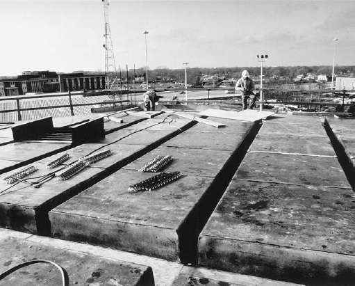
FIGURE 14.26 Formwork for a wide-module concrete joist system. These pans have been placed over a flat plywood deck, which will also serve to form the bottoms of the joist band beams. (Courtesy of the Ceco Corporation, Oakbrook Terrace, Illinois)
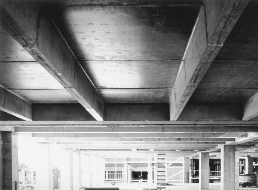
FIGURE 14.27 The underside of the finished wide-module joists, joist bands, and slab. (Courtesy of the Ceco Corporation, Oakbrook Terrace, Illinois)
Leave a Reply