
This section briefly reviews other renewable energy systems. Most of these, except wind energy, are not covered in this book. More details on these systems can be found in other publications.
Wind energy
Wind is generated by atmospheric pressure differences, driven by solar power. Of the total of 175,000 TW of solar power reaching the earth, about 1200 TW (0.7%) are used to drive the atmospheric pressure system. This power generates a kinetic energy reservoir of 750 EJ with a turnover time of 7.4 days (Soerensen, 1979). This conversion process takes place mainly in the upper layers of the atmosphere, at around 12 km height (where the “jet streams” occur). If it is assumed that about 4.6% of the kinetic power is available in the lowest strata of the atmosphere, the world wind potential is on the order of 55 TW. Therefore it can be concluded that, purely on a theoretical basis and disregarding the mismatch between supply and demand, the wind could supply an amount of electrical energy equal to the present world electricity demand.
As a consequence of the cubic (to the third power) relationship between wind speed and wind power (and hence energy), one should be careful in using average wind speed data (m/s) to derive wind power data (W/m2). Local geographical circumstances may lead to mesoscale wind structures, which have a much higher energy content than one would calculate from the most commonly used wind speed frequency distribution (Rayleigh). Making allowances for the increase of wind speed with height, it follows that the energy available at, say, 25 m varies from around 1.2 MWh/m2/a to around 5 MWh/m2/a in the windiest regions. Higher energy levels are possible if hilly sites are used or local topography funnels a prevailing wind through valleys.
A brief historical introduction into wind energy
In terms of capacity, wind energy is the most widely used renewable energy source. Today there are many wind farms that produce electricity. Wind energy is, in fact, an indirect activity of the sun. Its use as energy goes as far back as 4000 years, during the dawn of historical times. It was adored, like the sun, as a god. For the Greeks, wind was the god Aeolos, the “flying man”. After this god’s name, wind energy is sometimes referred to as Aeolian energy (Delyannis, 2003).
In the beginning, about 4000 years ago, wind energy was used for the propulsion of sailing ships. In antiquity, this was the only energy available to drive ships sailing in the Mediterranean Basin and other seas, and even today, it is used for sailing small leisure boats. At about the same period, windmills, which were used mainly to grind various crops, appeared (Kalogirou, 2005).
It is believed that the genesis of windmills, though not proven, lay in the prayer mills of Tibet. The oldest very primitive windmills have been found at Neh, eastern Iran, and on the Afghanistan border (Major, 1990). Many windmills have been found in Persia, India, Sumatra, and Bactria. It is believed, in general, that many of the windmills were constructed by the Greeks, who immigrated to Asia with the troops of Alexander the Great (Delyannis, 2003). The earliest written document about windmills is a Hindu book of about 400 BC, called Arthasastra of Kantilys, in which there is a suggestion for the use of windmills to pump water (Soerensen, 1995). The next known record is from the Hero of Alexandria who described it in the first century AD. In Western Europe, windmills came later, during the twelfth century, with the first written reference in the 1040–1180 AD time frame (Merriam, 1980). Originally in the twelfth century, these were of the post-mill type in which the whole apparatus was mounted on a post so that it could be rotated to face the wind, and later in the fourteenth century, these were of the tower-mill type where only the top part of the windmill carrying the sails could be rotated (Sorensen, 2009a). The industrial revolution and the advent of steam power brought an end to the use of windmills.
A new use of the wind power was connected to the invention of the water pump and used extensively originally by farmers in the United States and subsequently in many parts of the world. This is of the classic lattice metal tower carrying a rotor made from galvanized steel vanes known as the California-type wind pumps (Sorensen, 2009a).
The famous Swiss mathematician, Leonhard Euler, developed the wind wheel theory and related equations, which are, even today, the most important principles for turbogenerators. The ancestor of today’s vertical axis wind turbines was developed by Darrieus (1931), but it took about 50 years to be commercialized, in the 1970s. Scientists in Denmark first installed wind turbines during the Second World War to increase the electrical capacity of their grid. They installed 200 kW Gedser mill turbines, which were in operation until the 1960s (Dodge and Thresler, 1989).
Wind energy systems technology
The exploitation of wind energy today uses a wide range of machine sizes and types, giving a range of different economic performances. Today there are small machines up to about 300 kW and large-capacity ones that are in the megawatt range. A photograph of a wind park is shown in Figure 1.8.
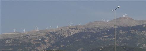
FIGURE 1.8 A photograph of a wind park.
The technology of the wind turbine generators currently in use is only 25 years old, and investment in it so far has been rather modest, compared with other energy sources. Nearly all the wind turbines manufactured by industry are of the horizontal axis type, and most of them have a three-bladed rotor. However, for some years now, machines have been constructed with two blades to reduce the costs and prolong the life of machines by making them lighter and more flexible by reducing the number of high-technology components.
Europe installed 9616 MW of wind turbines in 2011, an increase of 11% over the installation levels of 2010. The market for European wind power capacity broke new records in 2011, according to annual statistics from the European Wind Energy Association. The cumulative wind capacity in the EU increased to 93,957 MW, which can generate 190 TWh of electricity in an average wind year, equal to 6.3% of total EU power consumption. Worldwide by the end of 2011, 238 GW were installed, an increase of 40.5 GW from 2010. These wind turbines have the capacity to generate 500 TWh per year electricity, which is equal to about 3% of the world electricity usage. During the period 2005–2010 the installed wind turbines show an average increase of 27.6%.
Germany and Spain continue to be the leading countries in installed wind power with 29,060 and 21,674 MW, respectively. There is however a healthy trend in the European market toward less reliance on Germany and Spain as all other EU countries except Slovenia and Malta are investing in this technology. In 2011, 6480 MW of European wind capacity was installed outside Germany and Spain. On the total installed wind power except Germany and Spain the leading countries are France with 6800 MW, Italy with 6747 MW and United Kingdom with 6540 MW.
It is clear that this investment is due to the strong effect of the EU Renewable Electricity Directive passed in 2001, which urges the EC and the council to introduce safeguard measures that ensure legal stability for renewable electricity in Europe. These figures confirm that sector-specific legislation is the most efficient way to boost renewable electricity production.
Germany installed 2086 MW of turbines in 2011, 39% more than in 2010, and is very near the 30,000 MW mark of total installed wind power. Spain was the second largest market, with 1050 MW (1463 MW in 2010, a drop of 28%), while United Kingdom moved into third place by installing 1293 MW during 2011, 29% more than in 2010. In 2011, Italy installed 950 MW of new capacity, France installed 830 MW and Sweden installed 763 MW. Cyprus, a country with no previous record of wind power, has now 134 MW of installed power. Wind energy in the new EU-12 countries reached 4287 MW in 2011. Fourteen countries in the EU have now surpassed the 1000 MW threshold of wind capacity.
The investments made to achieve this level of development have led to a steady accumulation of field experience and organizational learning. Taken together, many small engineering improvements, better operation and maintenance practices, improved wind prospects, and a variety of other incremental improvements have led to steady cost reductions.
Technological advances promise continued cost reductions. For example, the falling cost of electronic controls has made it possible to replace mechanical frequency controls with electronic systems. In addition, modern computer technology has made it possible to substantially improve the design of blades and other components.
The value of wind electricity depends on the characteristics of the utility system into which it is integrated, as well as on regional wind conditions. Some areas, particularly warm coastal areas, have winds with seasonal and daily patterns that correlate with demand, whereas others have winds that do not. Analyses conducted in the United Kingdom, Denmark, and the Netherlands make it clear that wind systems have greater value if numerous generating sites are connected, because it is likely that wind power fluctuations from a system of turbines installed at many widely separated sites will be less than at any individual site.
More details on wind energy systems can be found in Chapter 13.
Biomass
Biomass energy is a generic term applied to energy production achieved from organic material broken down into two broad categories:
• Woody biomass. Forestry timber, residues and co-products, other woody material including thinning and cleaning from woodlands (known as forestry arisings), untreated wood products, energy crops such as willow, short rotation coppice, and miscanthus (elephant grass).
• Non-woody biomass. Animal wastes, industrial and biodegradable municipal products from food processing, and high-energy crops such as rape, sugarcane, and corn.
Biomass, mainly in the form of industrial and agricultural residues, provided electricity for many years with conventional steam turbine power generators. The United States currently has more than 8000 MWe of generating capacity fueled from biomass. Existing steam turbine conversion technologies are cost competitive in regions where low-cost biomass fuels are available, even though these technologies are comparatively inefficient at the small sizes required for biomass electricity production.
The performance of biomass electric systems can be improved dramatically by adapting to biomass advanced gasification technologies developed originally for coal. Biomass is a more attractive feedstock for gasification than coal because it is easier to gasify and has very low sulfur content; therefore, expensive sulfur removal equipment is not required. Biomass integrated gasifier–gas turbine power systems with efficiencies of more than 40% have been commercially available since the early 1990s. These systems offer high efficiency and low unit capital costs for base load power generation at relatively modest scales of 100 MWe or less and can compete with coal-fired power plants, even when fueled with relatively costly biomass feed stocks.
Another form of energy related to agriculture is biogas. Animal waste is usually used for the generation of electricity from biogas. In these systems, the manure from animals is collected and processed to produce methane, which can be used directly in a diesel engine driving a generator to produce electricity. This can be achieved with two processes; aerobic and anaerobic digestion. Aerobic digestion is the process that takes place in the presence of oxygen, whereas the term anaerobic means without air and hence anaerobic digestion refers to the special type of digestion, which takes place without oxygen. All animal manures are valuable sources of bioenergy. These are usually processed with anaerobic digestion. Anaerobic digestion offers solutions designed to control and accelerate the natural degradation process that occurs in stored manure. An anaerobic digester is a completely closed system, which allows more complete digestion of the odorous organic intermediates found in stored manure to less offensive compounds (Wilkie, 2005). Similar benefits can be obtained also from the aerobic digestion but its operational costs and complexity are greater than the anaerobic systems. Additionally, aerobic methods consume energy and produce large amounts of by-product sludge, which requires disposal compared with significantly less sludge produced in the anaerobic process. From the process engineering point of view, anaerobic digestion is relatively simple, even though the biochemical processes involved are very complex (Wilkie, 2005). Anaerobic digestion applications can be at ambient temperature (15–25 °C), mesophilic temperature (30–40 °C), or thermophilic (50–60 °C) temperature, while farm digesters usually operate at mesophilic temperatures. For these systems to be feasible, large farms or consortiums of farms are required. This method also solves the problem of disposing of the manure, and as a by-product, we have the creation of a very good fertilizer. In the following subsections only biomass and biofuels are examined.
Sustainable biomass production for energy
The renewable energy-intensive global scenario described in Section 1.2 calls for some 400 million hectares of biomass plantations by the second quarter of the twenty-first century. If this magnitude of biomass is used, the questions raised are whether the net energy balances are sufficiently favorable to justify the effort, whether high biomass yields can be sustained over wide areas and long periods, and whether such plantations are environmentally acceptable (Johanson et al., 1993).
Achieving high plantation yields requires energy inputs, especially for fertilizers and harvesting and hauling the biomass. The energy content of harvested biomass, however, is typically 10–15 times greater than the energy inputs.
However, whether such high yields can be achieved year after year is questionable. The question is critical because essential nutrients are removed from a site at harvest; if these nutrients are not replenished, soil fertility and yields will decline over time. Fortunately, replenishment is feasible with good management. Twigs and leaves, the parts of the plant in which nutrients tend to concentrate, should be left at the plantation site at harvest, and the mineral nutrients recovered as ash at energy conversion facilities should be returned to the plantation soils. Nitrogen losses can be restored through the application of chemical fertilizers; make-up requirements can be kept low by choosing species that are especially efficient in the use of nutrients. Alternatively, plantations can be made nitrogen self-sufficient by growing nitrogen-fixing species, perhaps intermixed with other species. In the future, it will be possible to reduce nutrient inputs by matching nutrient applications to a plant’s cyclic needs.
Intensive planting and harvesting activities can also increase erosion, leading to productivity declines. Erosion risks for annual energy crops would be similar to those for annual food crops, and so the cultivation of such crops should be avoided on erodible lands. For crops such as trees and perennial grasses, average erosion rates are low because planting is so infrequent, typically once in every 10–20 years.
An environmental drawback of plantations is that they support far fewer species than natural forests. Accordingly, it is proposed here that plantations be established not on areas now occupied by natural forests but instead on deforested and otherwise degraded lands in developing countries and on excess agricultural lands in industrialized countries. Moreover, a certain percentage of land should be maintained in a natural state as sanctuary for birds and other fauna, to help control pest populations. In short, plantations would actually improve the status quo with regard to biological diversity.
Biofuels
Recent advancements in distillation and blending technologies are being widely recognized as influencing the global proliferation of biofuels. The idea of biofuels is not new; in fact, Rudolf Diesel envisaged the significance of biofuels back in the nineteenth century, stating, “The use of vegetable oils for engine fuels may seem insignificant today. But such oils may become in the course of time, as important as petroleum and the coal tar products of the present time” (Cowman, 2007).
Rudolf Diesel’s first compression ignition engines ran on peanut oil at the World Exposition in Paris. The current drive toward greater use of biofuels is being pushed by the diversification of energy sources using renewable products, as reliance on carbon-based fuels becomes an issue, and the need to replace the methyl tertiary butyl ether (MTBE) component used in many of the world’s petroleum products. The change from fuels with an MTBE component started as an environmental issue in various parts of the world.
Ethanol has been recognized as the natural choice for replacing MTBE, and the need for blending ethanol into petroleum products is now a global requirement. Brazil has long been the world’s leader when it comes to fuel ethanol capacity, but the United States is trying to exceed this and other countries in the Western Hemisphere by rapidly growing its production. European legislation has set substantial targets for the coming years, and EU Directive 2003/30/EC promoting the use of biofuels in transport set a target of 5.75% use by 2010. Under the Directive 2009/28/EC on the promotion of the use of energy from renewable sources this share rises to a minimum of 10% in every Member State in 2020. Regarding the expansion of biofuels’ use in the EU, the Directive aims to ensure the use of sustainable biofuels only, which generate a clear and net GHG saving without negative impact on biodiversity and land use. Standards for biofuels have already been established, with the undiluted base products being defined as B100 (100% biodiesel) and El00 (100% ethanol). Subsequent blending will modify this number, such as a blend of 80% petrol and 20% ethanol, defined as E20, or a blend of 95% diesel and 5% biodiesel, defined as B5 (Cowman, 2007).
Biodiesel can be used in any concentration with petroleum-based diesel fuel, and little or no modification is required for existing diesel engines. Biodiesel is a domestic renewable fuel for diesel engines and is derived from vegetable oils and animal fats, including used oils and fats. Soybean oil is the leading vegetable oil produced in the United States and the leading feedstock for biodiesel production. Biodiesel is not the same as a raw vegetable oil; rather, it is produced by a chemical process that removes the glycerin and converts the oil into methyl esters.
Utilizing the current petroleum distribution infrastructure, blending is typically carried out at the storage or loading terminal. The most common locations for blending are the storage tank, the load rack headers, or most effectively, at the load arm. The most important requirement for this process is the accurate volume measurement of each product. This can be done through sequential blending or ratio blending but most beneficially utilizing the side stream blending technique.
Although petroleum products containing MTBE could be blended at the refinery and transported to the truck or tanker loading terminals via a pipeline or railcar, ethanol-blended fuel contains properties that make this difficult. Ethanol, by nature, attracts any H2O encountered on route or found in storage tanks. If this happens in a 10% blend and the concentration of H2O in the blended fuel reaches 0.4%, the combined ethanol and H2O drop out of the blend. The exact point of dropout depends on the ethanol percentage, make-up quantity, and temperature. If this dropout occurs, the ethanol combines with the H2O and separates from the fuel, dropping to the bottom of the storage tank. The resulting blend goes out of specification, and getting back to the correct specification requires sending the contaminated ethanol back to the production plant.
The solution to this problem is to keep the ethanol in a clean, dry environment and blend the ethanol with the petroleum products when loading the transport trucks and tankers. Moving the blend point to the loading point minimizes the risk of fuels being contaminated by H2O.
In general biodiesel processing, the fat or oil is degummed and then reacted with alcohol, such as methanol, in the presence of a catalyst to produce glycerin and methyl esters (biodiesel). Methanol is supplied in excess to assist in quick conversion, and the unused portion is recovered and reused. The catalyst employed is typically sodium or potassium hydroxide, which has already been mixed with the methanol (Cowman, 2007).
Although fuel produced from agriculture has had only marginal use in today’s climate, there are political, environmental, legislative, and financial benefits for using biofuels. With oil prices remaining high and very unlikely to reduce, demand for biofuel will continue to rise and provide exciting growth prospects for both investors and equipment manufacturers.
Geothermal energy
Measurements show that the ground temperature below a certain depth remains relatively constant throughout the year. This is because the temperature fluctuations at the surface of the ground are diminished as the depth of the ground increases due to the high thermal inertia of the soil.
There are different geothermal energy sources. They may be classified in terms of the measured temperature as low (<100 °C), medium (100–150 °C), and high temperature (>150 °C). The thermal gradient in the earth varies between 15 and 75 °C per km depth; nevertheless, the heat flux is anomalous in different continental areas. The cost of electrical energy is generally competitive, 0.6–2.8 U.S. cents/MJ (2–10 U.S. cents/kWh), and 0.3%, or 177.5 billion MJ/a (49.3 billion kWh/a), of the world total electrical energy was generated in the year 2000 from geothermal resources (Baldacci et al., 1998).
Geothermal power based on current hydrothermal technology can be locally significant in those parts of the world where there are favorable resources. About 6 GWe of geothermal power were produced in the early 1990s and 15 GWe may be added during the next decade. If hot dry rock geothermal technology is successfully developed, the global geothermal potential will be much larger.
Deep geothermal heat plants operate with one- or two-hole systems. The high expenditure incurred in drilling holes discourages one from using this method in gaining thermal energy. The one-hole injection system or the use of existing single holes, made during crude oil or natural gas exploration, reduces the capital cost. In one-hole systems, the hole is adapted to locate in it a vertical exchanger with a double-pipe heat exchanger, in which the geothermal water is extracted via the inside pipe. Published characteristics allow the estimation of the gained geothermal heat energy flux as a function of the difference between the temperatures of extracted and injected water at different volume fluxes of the geothermal water. In general, the two-layer systems and two-hole systems are more advantageous than one-hole systems. More details of geothermal systems related to desalination are given in Chapter 8.
Ground coupled heat pumps
In these systems ground heat exchangers (GHE) are employed to exchange heat with the ground (see Chapter 8, Section 8.5.6). The ground can be used as an energy source, an energy sink, or for energy storage (Eckert, 1976). For the efficient use of the ground in energy systems, its temperature and other thermal characteristics must be known. Studies show that the ground temperature varies with depth. At the surface, the ground is affected by short-term weather variations, changing to seasonal variations as the depth increases. At deeper layers, the ground temperature remains almost constant throughout the seasons and years and is usually higher than that of the ambient air during the cold months of the year and lower during the warm months (Florides and Kalogirou, 2008). The ground therefore is divided into three zones:
1. The surface zone where hourly variations of temperature occur,
2. The shallow zone, with monthly variations, and
3. The deep zone, where the temperature is almost constant year round.
The structure and physical properties of the ground are factors affecting temperature, in all zones. The temperature of the ground is a function of the thermal conductivity, specific heat, density, geothermal gradient, water content, and water flow rate through the ground. Studies carried out in several locations in Cyprus (typical Mediterranean climate) show that according to the formation of the ground the surface zone reaches a depth of 0.5 m. The shallow zone penetrates to 7–8 m and there after the deep zone follows. Furthermore, the temperature of the ground of the island at the deep zone has a range between 18 and 23 °C (Florides and Kalogirou, 2008).
GHE or earth heat exchangers (EHE), are devices used for the exploitation of the ground thermal capacity and the difference in temperature between ambient air and ground. A GHE is usually an array of buried pipes installed either horizontally or vertically into the ground. They use the ground as a heat source when operating in the heating mode and as a heat sink when operating in the cooling mode, with a fluid, usually air, water or a water–antifreeze mixture, to transfer the heat from or to the ground. They can contribute to the air-conditioning of a space, for water heating purposes and also for improving the efficiency of a heat pump.
Ground-coupled heat pumps (GCHPs) or geothermal heat pumps are systems combining a heat pump with a GHE for the heat exchange process, which improves the heat pump efficiency. Mainly, they are of two types; namely, the ground-coupled (closed-loop) system or the groundwater (open-loop) system. The type to be used is chosen according to the ground thermal characteristics, the available land for installation, and the groundwater availability and temperature.
Common heat pumps use an electrically driven compressor that compresses a refrigerant and raises its pressure and thus its temperature. The refrigerant has the ability to change state, from liquid to gas when heated and usually it boils at low temperatures. In the heating mode, the common heat pump’s refrigerant absorbs heat from the environment and becomes gas. Then the gas is compressed mechanically and has its temperature increased. The refrigerant at this stage is of high pressure and temperature and exchanges heat with a lower temperature medium (gas or liquid) as it passes through a condenser heating the conditioned space. Having its temperature dropped it returns to the liquid stage and after passing through an expansion valve it becomes liquid at low temperature and pressure. Then the process starts all over again with the refrigerant absorbing heat from the environment cooling it as it passes through an evaporator.
GCHPs exchange heat with the ground instead of the atmosphere. An EHE and a liquid circulating pump are parts that are not included in common heat pumps and are used in the heat exchange process. The heat pumps can be used for both heating and cooling of buildings. This is achieved by reversing the cycle, which means that the condenser and evaporator reverse their roles. The efficiency of heat pumps is described by the coefficient of performance (COP) in the heating mode and the energy efficiency ratio (EER) in the cooling mode. The COP or EER is the ratio of the rate of net heat output to the total energy input expressed in consistent units and under designated rating conditions or is the ratio of the refrigerating capacity to the work absorbed by the compressor per unit time. Sometimes the efficiency is described by the seasonal performance factor, which is the average efficiency of the pump over the heating and cooling period or the seasonal energy efficiency ratio for cooling, which is the total cooling output of an air conditioner during its normal annual usage period for cooling divided by the total electric energy input during the same period. The COP or EER of GCHPs usually is higher than those of the common heat pumps and especially their seasonal performance factor, due to the fact that the ground temperature is more stable during the year, cooler in summer, and hotter in winter than the ambient air (Florides et al., 2011).
Both types of GHEs, open or closed loop, are pollutant free since the only effect they have on the ground is the small increase or decrease of its temperature in a certain distance around the borehole. The efficiency of GCHP depends on the temperature of the cold reservoir (TC) and the temperature of the hot reservoir (TH). For the same value of TC, the efficiency of the refrigerator becomes greater when TH is lower, that is the smaller the difference between TH and TC, the greater the COP. In equation form the ideal reversible Carnot cycle COP is given by:
![]() (1.1)
(1.1)
For example, calculating the thermodynamic COP of an ideal air-conditioning unit, working at an environmental temperature of 35 °C and a room temperature of 20 °C, with 5 °C expansion temperature and 60 °C compression temperature, we get a thermodynamic COP of 5.05 [= 278/(333 − 278)]. It should be noted that this number will be around 3.7 for an actual unit. By keeping the same variables as above, but reverting into a ground-coupled refrigerator exchanging heat with the ground at 22 °C and with the compression temperature reduced to 35 °C instead of 60 °C, the thermodynamic COP increases to 9.26 [= 278/(308 − 278)] with obvious advantages in electricity consumption. Again in this case, the COP for an actual unit is around 7.7. GCHPs are considered to be improvement on the common water-cooled heat pumps.
Hydrogen
Hydrogen, though the most common element in the universe, is not found in its pure form on earth and must be either electrolyzed from water or stripped out from natural gas, both of which are energy-intensive processes that result in GHG emissions. Hydrogen is an energy carrier and not a fuel, as is usually wrongly asserted. Hydrogen produced electrolytically from wind or direct solar power sources and used in fuel cell vehicles can provide zero-emission transportation. As for any fuel, appropriate safety procedures must be followed. Although the hazards of hydrogen are different from those of the various hydrocarbon fuels now in use, they are not greater.
The basic question is how to produce hydrogen in a clean efficient way. Using natural gas, coal, or even nuclear power to produce hydrogen in many ways defeats the purpose of moving toward a future powered by hydrogen. In the first two instances, GHGs are emitted in the process of producing the hydrogen, whereas in the last case, nuclear waste is generated.
As a nearly ideal energy carrier, hydrogen will play a critical role in a new decentralized energy infrastructure that can provide power to vehicles, homes, and industries. However, the process of making hydrogen with fossil-based power can involve the emission of significant levels of GHGs.
Although the element of hydrogen is the most abundant one in the universe, it must be extracted from biomass, water, or fossil fuels before it can take the form of an energy carrier. A key issue in the future is to promote the generation of electricity from wind and then use that electricity to produce hydrogen.
Extracting hydrogen from water involves a process called electrolysis, defined as splitting elements apart using an electric current. Energy supplied from an external source, such as wind or the burning of a fossil fuel, is needed to drive the electrochemical reaction. An electrolyzer uses DC to separate water into its component parts, hydrogen and oxygen. Supplementary components in the electrolyzer, such as pumps, valves, and controls, are generally supplied with AC from a utility connection. Water is “disassociated” and ions are transported through the electrolyte. Hydrogen is collected at the cathode and oxygen at the anode. The process requires pure water.
Electrolysis of water is the decomposition of water (H2O) into oxygen (O2) and hydrogen (H2) gas. This is achieved by passing an electric current through the water.
As shown schematically in Figure 1.9, an electric DC power source is connected to two electrodes, which usually are in the form of plates to increase the surface area, typically made from inert metals (platinum or stainless steel). By doing so hydrogen appears at the cathode, the negatively charged electrode, and oxygen will appear at the anode, the positively charged electrode. Under ideal conditions, the number of moles of hydrogen generated is twice the number of moles of oxygen.
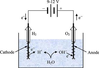
FIGURE 1.9 Schematic diagram of the process of electrolysis.
Electrolysis of pure water requires excess energy otherwise the process is very slow. The efficiency of electrolysis is increased with the addition of an electrolyte, such as a salt, an acid, or a base. If electrolysis is applied in pure water, H+ cations will accumulate at the anode and hydroxyl OH− anions will accumulate at the cathode. Unless a very large potential is applied electrolysis of pure water is very slow, limited by the overall conductivity.
If a water-soluble electrolyte is added, the conductivity of the water increases considerably. The electrolyte disassociates into cations and anions; the anions move toward the anode and neutralize the buildup of positively charged H+, whereas the cations move toward the cathode and neutralize the buildup of negatively charged OH−.
Industrial electrolysis cells are very similar to basic unit shown in Figure 1.9, using platinum plates or honeycombs as electrodes in an attempt to increase the electrode’s surface area.
Two variations of the basic process are the high-pressure and high-temperature electrolysis. In high-pressure electrolysis hydrogen is compressed at around 120–200 bar. By pressurizing the hydrogen in the electrolyzer, the need for an external hydrogen compressor is eliminated whereas the average energy consumption for internal compression is very small of the order of 3%. High-temperature electrolysis, also called steam electrolysis, can combine electrolysis with a heat engine. High temperature increases the efficiency of electrolysis reaction and the process is very effective as generally heat energy is cheaper than electricity.
Despite considerable interest in hydrogen, however, there is a significant downside to producing it by means of fossil fuel-generated electricity due to the emissions related to the electrolysis process. Hydrogen fuel promises little GHG mitigation if a developing hydrogen economy increases demand for fossil fuel electricity. On the other hand, using cleanly produced hydrogen can fundamentally change our relationship with the natural environment.
Electrolytic hydrogen may be attractive in regions such as Europe, South and East Asia, North Africa, and the southwestern United States, where prospects for biomass-derived fuels are limited because of either high population density or lack of water. Land requirements are small for both wind and direct solar sources, compared with those for biomass fuels. Moreover, as with wind electricity, producing hydrogen from wind would be compatible with the simultaneous use of the land for other purposes such as ranching or farming. Siting in desert regions, where land is cheap and insolation is good, may be favored for PV–hydrogen systems because little water is needed for electrolysis. The equivalent of 2–3 cm of rain per year on the collectors—representing a small fraction of total precipitation, even for arid regions—would be enough.
Electrolytically produced hydrogen will probably not be cheap. If hydrogen is produced from wind and PV electricity, the corresponding cost of pressurized electrolytic hydrogen to the consumer would be about twice that for methanol derived from biomass; moreover, a hydrogen fuel cell car would cost more than a methanol fuel cell car because of the added cost for the hydrogen storage system. Despite these extra expenses, the life-cycle cost for a hydrogen fuel cell car would be marginally higher than for a gasoline internal combustion engine car, which is about the same as for a battery-powered electric vehicle.
The transition to an energy economy in which hydrogen plays a major role could be launched with hydrogen derived from biomass. Hydrogen can be produced thermochemically from biomass using the same gasifier technology that would be used for methanol production. Although the downstream gas processing technologies would differ from those used for methanol production, in each case the process technologies are well established. Therefore, from a technological perspective, making hydrogen from biomass is no more difficult than making methanol. Biomass-derived hydrogen delivered to users in the transport sector would typically cost only half as much as hydrogen produced electrolytically from wind or PV sources.
Probably the best way to utilize hydrogen is with a fuel cell. A fuel cell is an electrochemical energy conversion device in which hydrogen is converted into electricity. Generally, fuel cells produce electricity from external supplies of fuel (on the anode side) and oxidant (on the cathode side). These react in the presence of an electrolyte. Generally, the reactants flow in and reaction products flow out while the electrolyte remains in the cell. Fuel cells can operate continuously as long as the necessary flows are maintained. A hydrogen cell uses hydrogen as fuel and oxygen as an oxidant. Fuel cells differ from batteries in that they consume reactants, which must be replenished, whereas batteries store electrical energy chemically in a closed system. Additionally, while the electrodes within a battery react and change as a battery is charged or discharged, a fuel cell’s electrodes are catalytic and relatively stable. More details on fuel cells are given in Chapter 7.
Ocean energy
The various forms of ocean energy are abundant but often available far away from the consumer sites. The world’s oceans have the capacity to provide cheap energy. Right now, there are very few ocean energy power plants, and most are fairly small.
The energy of the ocean can be used in three basic ways (Energy Quest, 2007):
• Use the ocean’s waves (wave energy conversion).
• Use the ocean’s high and low tides and tide currents (tidal energy conversion).
• Use temperature differences in the water (ocean thermal energy conversion (OTEC)).
Unlike other renewable energy sources that rely on sophisticated technologies and advanced materials, such as PVs, most ocean renewable energy systems are inherently simple, since they are made from concrete and steel. Additionally, most of the ocean systems rely on proven technologies, such as hydraulic rams and low-head hydropower turbines and impellers. The ocean’s energy resource is large and well understood. It is superior to wind and solar energy, since ocean waves and currents traveling in deep water maintain their characteristics over long distances and the state of the sea can easily be predicted accurately more than 48 h in advance. Therefore, although wave energy is variable, like all renewable energy sources, it is more predictable than solar or wind energy. Similarly, tidal currents are created because of the interaction of the tides and the ocean floor and are thus very predictable and generally more constant than wind and solar energy. Additionally, the high density of water makes the resource concentrated, so moving water carries a lot of energy (Katofsky, 2008). The disadvantage of ocean systems is the need to apply mechanical systems that must be robust and withstand the harsh marine environment.
Wave energy conversion systems convert the kinetic energy of the waves into mechanical energy directly to drive a generator to produce electricity in a special construction, where the oscillating movement of waves is converted into air pressure. This in sequence drives a special wind turbine to produce electricity. Obviously the larger the relative height of the waves, the better. The waves must also be present for many hours of the year.
Tidal energy systems again utilize special turbines or propellers located underwater, which convert the movement of the water due to the tide into mechanical energy to drive an electric generator to produce electricity. Tide is a consequence of the rotation of the moon around the earth and local geography of the seafloor and coastlines. These systems are feasible in places where the tide distance is extended to hundreds of meters. The greatest advantage of these systems is that tides are easily predictable.
Finally, the OTEC systems use the temperature difference of surface and deep water to produce energy. Rankine cycle using a low-pressure turbine is the most employed heat cycle for OTEC. Both closed-cycle and open-cycle engines can be employed. Closed-cycle engines use refrigerants (ammonia or R-134a) as the working fluids, whereas open-cycle engines use vapor produced from the seawater itself as the working fluid. OTEC can also supply cold water as a by-product, which can be used for air-conditioning and refrigeration.
The various ocean energy systems are described briefly in the following sections.
Wave energy
Wave power is the transport of energy by ocean surface waves and the harnessing of that energy to produce useful work such as electricity generation and seawater desalination. The equipment used to exploit wave power is called a wave energy converter (WEC).
Kinetic energy (movement) exists in the moving waves of the ocean and can be used to power a turbine. These systems fundamentally convert the kinetic energy of the waves into electricity by capturing either the vertical oscillation or the linear motion of the waves. Individual devices range in sizes of about 100 kW to about 2 MW (Katofsky, 2008). In the simple example shown in Figure 1.10, the wave rises into a chamber. The rising water forces the air out of the chamber. The moving air spins a turbine that can turn a generator. When the wave goes down, air flows through the turbine and back into the chamber through doors that are normally closed.
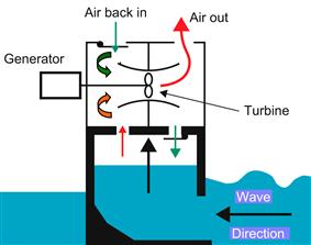
FIGURE 1.10 Principle of operation of a wave energy converter.
This is only one type of wave energy system. Others actually use the up-and-down motion of the wave to power a piston that moves up and down inside a cylinder. That piston can also turn a generator. Most wave energy systems are very small and are applied mainly to power a warning buoy or small lighthouses.
Although a massive potential exists, wave power generation is not currently a widely employed commercial technology. The first attempts to use this power date back to 1890. Only quite recently, in 2008, the first experimental wave farm was opened in Portugal, at the Aguçadoura Wave Park.
Waves are generated by wind blowing over the surface of the seawater. When the waves propagate at a slower speed than the wind speed, at the boundary of the two media an energy transfer exists from the wind to the waves. The wave height is determined by wind speed, the depth, and topography of the seafloor and by the duration of time the wind is blowing. Generally, the larger the waves the more powerful they are whereas the wave power depends also on the water density and wave speed and wavelength. It should be noted that a matching practical limit exists and variations in time or distance will not produce larger waves and thus when this limit is reached, the waves are fully developed.
One of the first applications of wave power was constructed around 1910 by Bochaux-Praceique, used to power his house at Royan, a small seaside city near Bordeaux in France. This was the first oscillating water column-type WEC. Subsequently, the research on wave energy carried out by Yoshio Masuda in the 1940s was very important as he tested various concepts of wave energy devices at sea to power navigation lights.
The interest in wave energy was renewed in the 1970s, motivated by the first oil crisis. At this time a number of researchers re-investigated the potential of generating useful energy from ocean waves and some important inventions were produced, like the Salter’s or Edinburgh Duck developed by Stephen Salters in 1974. This unit attained a remarkable efficiency of 81% as the Duck’s curved cam-like body can stop 90% of wave motion and convert 90% of that energy to useful electricity. More recently, the interest in wave energy as a renewable energy system has grown due to climate change issues.
Wave power devices are mainly classified according to the method used to capture the wave energy (point absorber or buoy, oscillating water column, tapered channels, oscillating flaps), location (shoreline, nearshore and offshore), and the power delivery system (elastomeric hose pump, pump to shore, hydroelectric turbine, hydraulic ram, and air turbine). Parabolic or tapered channel reflectors are used to amplify the height of the wave and create a head of water, which can be used to drive a conventional low-head hydro turbine (Sorensen, 2009b). Another design uses a flap that oscillates because of the action of the moving waves like a pendulum and this motion can be converted into electricity using hydraulic rams (Sorensen, 2009b). Once this energy is captured and converted into electricity, power must be transported to the point of use or connected to the grid. Some of the important applications of WECs are the following:
• Protean WEC. When deployed this system sits on the ocean surface and converts the relative movement between the static ocean floor and the floating buoy into energy.
• Pelamis WEC. This consists of a series of semi-submerged cylindrical sections linked by hinged joints. As waves pass along the length of the converter the sections move relative to one another and the wave-induced motion of the sections is resisted by hydraulic cylinders, which pump high-pressure oil through hydraulic motors. Finally, the hydraulic motors drive the electrical generator to produce electricity.
• Wave Dragon energy converter. In the Wave Dragon large wing reflectors focus the waves up a ramp into an offshore reservoir. The water returns to the ocean by the force of gravity via hydroelectric generators.
Although wave energy conversion is still in the early development stage and a realistic picture of costs is impossible to be made, initial estimates give values of about €0.06–€0.12 per kWh (Sorensen, 2009b).
Tidal energy
Another form of ocean energy system is called tidal energy. This is a form of hydropower system that converts the energy of tides into electricity. When tides come into the shore, they can be trapped in reservoirs behind dams. Then when the tide drops, the water behind the dam can be allowed to flow, just like in a regular hydroelectric power plant. Tidal technologies can also employ underwater turbines or propellers driven by the flowing water. Such technologies can be deployed in streams and rivers as well.
Tidal energy has been used since about the eleventh century, when small dams were built along ocean estuaries and small streams. The tidal water behind these dams was used to turn water wheels to mill grains. Tidal barrage systems are in commercial operation in a few locations, but their further development is questionable because of their environmental impact in blocking off large estuaries (Katofsky, 2008).
Tidal energy works well when there is a large increase in tides. An increase of at least 5 m between low tide and high tide is needed. There are only a few places on earth where this tide change occurs.
Some power plants are already operating using this idea. One plant, the La Rance Station, in France, makes enough energy from tides (240 MW) to power 240,000 homes. It began making electricity in 1966. It produces about one-fifth of a regular nuclear or coal-fired power plant. It generates more than 10 times the power of the next largest tidal station in the world, the 17 MW Canadian Annapolis station.
Although tidal power is not widely adopted yet, it has the potential to supply large quantities of electricity in the near future. The greatest advantage of these systems compared with other renewable energy systems is that tides are more predictable than wind energy and solar power. Despite this, the costs involved are still relatively high and there is a limited availability of sites with high tidal potential. Many recent technological achievements in system and turbine designs, however, with the adoption of new axial and cross-flow turbines, give promise for a much lower cost of electricity produced.
Tidal forces are created because of the periodic variations in gravitational attraction exerted by celestial bodies, and they create motions or currents in the oceans of the earth. The intensity of this motion depends mainly on the earth rotation, the position of the moon and sun relative to the earth, and the local topography of the seafloor and coastline. The greatest effect is due to the orbital characteristics of the earth–moon system, and to a lesser extent in the earth–sun system. Because the earth’s tides and currents are due to the rotation of the earth and the gravitational interaction with the moon and sun, this form of energy resource is renewable and practically inexhaustible. Other currents are caused by geothermal gradients.
The conversion of tidal currents is similar to the conversion of kinetic energy from the wind. Therefore, many of the proposed designs to harness this potential have resemblances to the wind turbines. As the water density is much bigger than that of air much higher energy densities are present, which leads to lower exploitable current velocities and smaller diameter turbines.
A tidal generator converts the energy of tides and currents into useful electricity. As can be understood, the greater the tidal variation and the higher the tidal current velocities, the greater is the potential of a site for electricity generation. Tidal power can be classified into three generating methods:
• Tidal stream generator. Tidal stream generators use the kinetic energy of moving water to power turbines, similar to the way wind turbines use wind.
• Tidal barrage. Tidal barrages use the potential energy created because of the difference in hydrostatic height between high and low tides. Barrages are in fact dams constructed across the opening of a tidal estuary (see Figure 1.11).
• Dynamic tidal power. Dynamic tidal power is not applied yet. In principle it is a technology that could convert the kinetic energy in tidal flows or currents into useful electricity. Systems can be built into the sea or ocean, without enclosing an area. For this purpose wind-type turbines can be used underwater.
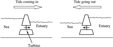
FIGURE 1.11 Principle of operation of tidal barrage.
A horizontal axis turbine comprises a propeller with two or more blades. The turbine can be mounted on a tower fixed to the seafloor, which is more suitable for shallow waters, or can be deployed below a floating support, for deep waters. To increase the efficiency of a horizontal axis turbine, the water flow around the turbine can be controlled with a shroud. These designs however are large underwater constructions and to avoid problems, sites of major shipping lanes and local fisheries must be avoided (Sorensen, 2009b).
Ocean thermal energy conversion
OTEC systems use the temperature difference of surface and deep water to make energy. This idea is not new but actually dates back to 1881, when a French engineer by the name of Jacques D’Arsonval first thought of OTEC. Ocean water gets colder the deeper you go from the surface, and at a great depth the ocean gets very cold. It is warmer on the surface because sunlight warms the water.
Power plants can be built that use this difference in temperature to make energy. A difference of at least 21 °C is needed between the warmer surface water and the colder deep ocean water. Using this type of energy source, an OTEC system is being demonstrated in Hawaii.
OTEC relies on the principle of thermodynamics that a source of heat and a source of cold can be used to drive a heat engine. It is well known from the laws of thermodynamics that a heat engine gives greater efficiency and power when a large temperature difference exists. In the oceans the temperature difference between surface and deep water is quite low in the order of 20–25 °C. So the main technical challenge of OTEC is to generate significant amounts of power efficiently from small temperature difference. The greatest temperature differences can be found in the tropics, and these offer the greatest possibilities for OTEC. Tropical oceans have surface water temperatures between 24 °C and 33 °C, whereas the temperature 500 m below the surface temperature drops between 9 °C and 5 °C (Sorensen, 2009b). Maps of the word showing the magnitude of the resource are presented by Rajagopalan and Nihous (2013). A temperature difference of about 20 °C gives a thermodynamic efficiency of 6.7% but when pumping energy is considered, this drops to about 3% as OTEC cycles must compensate with several cubic meters per second seawater flow rates per MW of net electricity produced. For example to generate 1 MW of electricity an OTEC plant requires 4 m3/s of warm seawater and 2 m3/s of cold seawater. To supply a 100 MW plant a pipe 11 m in diameter would be required (Sorensen, 2009b). These systems have the potential to offer great amounts of energy although a variation of 1 °C in the seawater thermal resource corresponds to a change in net power output of 15% (Rajagopalan and Nihous, 2013). OTEC plants, however, can operate continuously providing a base load supply of electrical power.
The first operational OTEC system was built in Cuba in 1930 and generated 22 kW. The most commonly used heat cycle for OTEC is the Rankine employing a low-pressure turbine and systems can be either closed cycle or open cycle. The former cycles use volatile working fluids (refrigerants) such as ammonia or R-134a, whereas open-cycle engines use vapor produced from the seawater. Useful by-products of OTEC system are the supply of large quantities of cold water, which can be used for air-conditioning or refrigeration and freshwater distilled from the sea, which can be used as a freshwater supply. Additionally the fertile deep ocean water can feed various biological processes. A schematic diagram of possible applications of OTEC is shown in Figure 1.12.
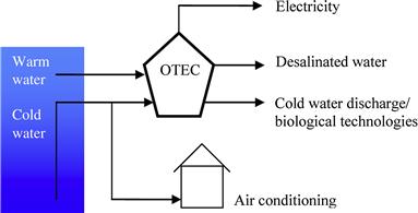
FIGURE 1.12 OTEC applications.
Three types of thermodynamic cycles can be used for OTEC; open, closed, and hybrid. One of the main problems is to pump the cold seawater from the deep ocean to the surface. This can be achieved by ordinary pumping and desalination. In the latter, desalinating seawater at the ocean floor lowers its density and this is the driving force to raise it to the surface. An alternative to high-cost pipes, which bring cold water to the surface, is to pump a vaporized low-boiling-point fluid into the required depth, which reduces pumping volume with consequent lowering of the costs. In any case OTEC plants require a long large diameter intake pipe, which is usually 1 km or more in length, to bring cold water to the surface.
Open-cycle OTEC uses warm surface water to produce electricity directly by pumping it in a low-pressure container, which causes its boiling. The expanding steam thus produced drives a low-pressure turbine/generator set. The steam produced in this way is pure freshwater, which is finally condensed by exposing it to cold temperatures from deep ocean water. This method produces also desalinated freshwater, which is an added advantage.
Closed-cycle systems use a fluid with low boiling point, such as ammonia or other refrigerants, expanding in a turbine so as to generate electricity. To achieve this, warm surface seawater is pumped through a heat exchanger to vaporize the volatile fluid. Cold water, which is pumped through a different heat exchanger, condenses the vapor, which is then recirculated through the system.
A hybrid cycle, as its name implies, combines the characteristics of both closed- and open-cycle systems. In these systems, warm seawater is fed in a vacuum chamber where it is flash evaporated, as in the open-cycle process. The steam thus produced vaporizes the working fluid, which is usually ammonia, of a closed-cycle loop on the other side of the evaporator. The vaporized working fluid then drives a turbine/generator unit while the steam condensed within the heat exchanger is used to produce desalinated water.
OTEC has the potential to produce large quantities of electrical power. For this purpose a number of systems have been proposed generally falling into three categories; land based, shelf based, and floating.
Land-based or near-shore facilities offer a number of advantages over those located in water; they do not require sophisticated mooring and lengthy power cables and compared with the open-ocean systems they require simple maintenance. These systems can be installed in sheltered areas to protect them from storms and the weather. Additionally, all products such as electricity, desalinated water, and cold water can be transmitted easily to the grid and water network.
Shelf-based OTEC plants can be mounted on a shelf at depths up to about 100 m to avoid the turbulent wave zone and to be closer to the cold water resource. This type of plant can be fixed to the sea bottom, similar to the way used for offshore oil rigs. Because of the conditions encountered by operating an OTEC plant in deeper water and open ocean, the expenditure involved is bigger compared with land-based systems. There are also problems associated with the difficulties related to the delivery of the produced electricity and freshwater. In fact, depending on the distance of the plant from the shore, power delivery can require long underwater cables, which makes shelf-mounted plants less attractive.
As their name implies, floating OTEC plants are located off-shore on special platforms and although they can be used for large power systems, they present a number of difficulties, for example related to the fixing of the platform with cables to the seabed and the power delivery. For the latter the problems are similar to those presented by the shelf-mounted system, whereas cables attached to floating platforms are more prone to damage, especially during heavy storms.
Leave a Reply