
Energy delivery temperatures can be increased by decreasing the area from which the heat losses occur. Temperatures far above those attainable by FPCs can be reached if a large amount of solar radiation is concentrated on a relatively small collection area. This is done by interposing an optical device between the source of radiation and the energy-absorbing surface. Concentrating collectors exhibit certain advantages over the conventional flat-plate type (Kalogirou et al., 1994a). The main advantages are as follows:
1. The working fluid can achieve higher temperatures in a concentrator system than a flat-plate system of the same solar energy-collecting surface. This means that a higher thermodynamic efficiency can be achieved.
2. It is possible with a concentrator system to achieve a thermodynamic match between temperature level and task. The task may be to operate thermionic, thermodynamic, or other higher temperature devices.
3. The thermal efficiency is greater because of the small heat loss area relative to the receiver area.
4. Reflecting surfaces require less material and are structurally simpler than FPCs. For a concentrating collector, the cost per unit area of the solar-collecting surface is therefore less than that of a flat-plate collector.
5. Owing to the relatively small area of receiver per unit of collected solar energy, selective surface treatment and vacuum insulation to reduce heat losses and improve the collector efficiency are economically viable.
Their disadvantages are as follows:
1. Concentrator systems collect little or no diffuse radiation, depending on the concentration ratio.
2. Some form of tracking system is required to enable the collector to follow the sun.
3. Solar reflecting surfaces may lose their reflectance with time and may require periodic cleaning and refurbishing.
Many designs have been considered for concentrating collectors. Concentrators can be reflectors or refractors, can be cylindrical or parabolic, and can be continuous or segmented. Receivers can be convex, flat, cylindrical, or concave and can be covered with glazing or uncovered. Concentration ratios, that is, the ratio of aperture to absorber areas, can vary over several orders of magnitude, from as low as slightly above unity to high values on the order of 10,000. Increased ratios mean increased temperatures at which energy can be delivered, but consequently, these collectors have increased requirements for precision in optical quality and positioning of the optical system.
Because of the apparent movement of the sun across the sky, conventional concentrating collectors must follow the sun’s daily motion. The sun’s motion can be readily tracked by two methods. The first is the altazimuth method, which requires the tracking device to turn in both altitude and azimuth, that is, when performed properly, this method enables the concentrator to follow the sun exactly. Paraboloidal solar collectors generally use this system. The second one is one-axis tracking, in which the collector tracks the sun in only one direction, either from east to west or north to south. Parabolic trough collectors (PTCs) generally use this system. These systems require continuous and accurate adjustment to compensate for the changes in the sun’s orientation. Relations on how to estimate the angle of incidence of solar radiation and the slope of the collector surface for these tracking modes are given in Chapter 2, Section 2.2.1.
The first type of solar concentrator, shown in Figure 3.14, is effectively a flat-plate collector fitted with simple flat reflectors, which can markedly increase the amount of direct radiation reaching the collector. This is, in fact, a concentrator because the aperture is bigger than the absorber but the system is stationary. A comprehensive analysis and model of such a system is presented by Garg and Hrishikesan (1998). The model facilitates the prediction of the total energy absorbed by the collector at any hour of the day for any latitude for random tilt angles and azimuth angles of the collector and reflectors. This simple enhancement of FPCs was initially suggested by Tabor (1966).
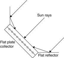
FIGURE 3.14 Flat-plate collector with flat reflectors.
FPCs can be equipped with flat reflectors, as shown in Figure 3.14 or with the saw-toothed arrangement shown in Figure 3.15, which is suitable for multi-row collector installations. In both cases, the simple flat diffuse reflectors can significantly increase the amount of direct radiation reaching the collector. The term diffuse reflector denotes a material that is not a mirror, avoiding the formation of an image of the sun on the absorber, which creates uneven radiation distribution and thermal stresses.
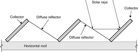
FIGURE 3.15 Flat-plate collectors with saw-toothed reflectors.
Another type of collector, the CPC, already covered under the stationary collectors, is also classified as concentrator. This can be stationary or tracking, depending on the acceptance angle. When tracking is used, this is very rough or intermittent, since the concentration ratio is usually small and radiation can be collected and concentrated by one or more reflections on the parabolic surfaces.
As was seen previously, one disadvantage of concentrating collectors is that, except at low concentration ratios, they can use only the direct component of solar radiation, because the diffuse component cannot be concentrated by most types. However, an additional advantage of concentrating collectors is that, in summer, when the sun rises well to the north of the east–west line, the sun follower, with its axis oriented north–south, can begin to accept radiation directly from the sun long before a fixed south-facing flat-plate collector can receive anything other than diffuse radiation from the portion of the sky that it faces. Thus, in relatively cloudless areas, the concentrating collector may capture more radiation per unit of aperture area than a flat-plate collector.
In concentrating collectors solar energy is optically concentrated before being transferred into heat. Concentration can be obtained by reflection or refraction of solar radiation by the use of mirrors or lenses. The reflected or refracted light is concentrated in a focal zone, thus increasing the energy flux in the receiving target. Concentrating collectors can also be classified into non-imaging and imaging, depending on whether the image of the sun is focused at the receiver. The concentrator belonging in the first category is the CPC, whereas all the other types of concentrators belong to the imaging type. The collectors falling into this category are:
1. Parabolic trough collector (PTC).
2. Linear Fresnel reflector (LFR).
3. Parabolic dish reflector (PDR).
4. Heliostat field collector (HFC).
3.2.1 Parabolic trough collector (PTC)
To deliver high temperatures with good efficiency a high-performance solar collector is required. Systems with light structures and low-cost technology for process heat applications up to 400 °C could be obtained with PTCs. PTCs can effectively produce heat at temperatures between 50 and 400 °C.
Parabolic trough collectors are made by bending a sheet of reflective material into a parabolic shape. A black metal tube, covered with a glass tube to reduce heat losses, is placed along the focal line of the receiver (see Figure 3.16). When the parabola is pointed toward the sun, parallel rays incident on the reflector are reflected onto the receiver tube. The concentrated radiation reaching the receiver tube heats the fluid that circulates through it, transforming the solar radiation into useful heat. It suffices to use a single-axis tracking of the sun; therefore, long collector modules are produced. The collector can be oriented in an east–west direction, tracking the sun from north to south, or in a north–south direction, tracking the sun from east to west. The advantages of the former tracking mode is that little collector adjustment is required during the day and the full aperture always faces the sun at noon but the collector performance during the early and late hours of the day is greatly reduced, due to large incidence angles (cosine loss). North–south oriented troughs have their highest cosine loss at noon and the lowest in the mornings and evenings, when the sun is due east or due west. Photographs of PTC collectors are shown in Figure 3.17.
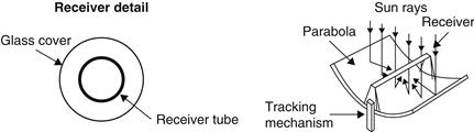
FIGURE 3.16 Schematic of a parabolic trough collector.
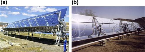
FIGURE 3.17 Photos of actual parabolic trough collectors. (a) The EuroTrough (from http://www.sbp.de/en#sun/show/1043-EuroTrough_Collector). (b) An Industrial Solar Technology collector.
Over a period of 1 year, a horizontal north–south trough field usually collects slightly more energy than a horizontal east–west one. However, the north–south field collects a lot of energy in summer and much less in winter (see Chapter 2, Section 2.2.1). The east–west field collects more energy in winter than a north–south field and less in summer, providing a more constant annual output. Therefore, the choice of orientation usually depends on the application and whether more energy is needed during summer or winter.
Parabolic trough technology is the most advanced of the solar thermal technologies because of considerable experience with the systems and the development of a small commercial industry to produce and market these systems. PTCs are built-in modules that are supported from the ground by simple pedestals at either end.
Parabolic trough collectors are the most mature solar technology to generate heat at temperatures up to 400 °C for solar thermal electricity generation or process heat applications. The biggest application of this type of system is the southern California power plants known as Solar Electric Generating Systems (SEGS), which have a total installed capacity of 354 MWe (Kearney and Price, 1992). SEGS I is 14 MWe, SEGS II–VII are 30 MWe each, and SEGS VIII and IX are 80 MWe each. Three collector designs have been used in these plants: LS-1 for SEGS I, LS-2 for SEGS II–VII, and LS-3 for part of SEGS VII, VIII, and IX. More details on this system are given in Chapter 10. Another important application of this type of collector is installed at Plataforma Solar de Almeria in southern Spain, mainly for experimental purposes, with a total installed capacity of the PTCs equal to 1.2 MW.
The receiver of a parabolic trough is linear. Usually, a tube is placed along the focal line to form an external surface receiver (see Figure 3.16). The size of the tube, and therefore the concentration ratio, is determined by the size of the reflected sun image and the manufacturing tolerances of the trough. The surface of the receiver is typically plated with a selective coating that has a high absorptance for solar radiation but a low emittance for thermal radiation loss.
A glass cover tube is usually placed around the receiver tube to reduce the convective heat loss from the receiver, thereby further reducing the heat loss coefficient. A disadvantage of the glass cover tube is that the reflected light from the concentrator must pass through the glass to reach the absorber, adding a transmittance loss of about 0.9, when the glass is clean. The glass envelope usually has an antireflective coating to improve transmissivity. One way to further reduce convective heat loss from the receiver tube and thereby increase the performance of the collector, particularly for high-temperature applications, is to evacuate the space between the glass cover tube and the receiver. The total receiver tube length of PTCs is usually from 25 to 150 m.
New developments in the field of PTCs aim at cost reduction and improvements in technology. In one system, the collector mirrors can be washed automatically, drastically reducing the maintenance cost.
After a period of research and commercial development of the PTCs in the 1980s a number of companies entered the field, producing this type of collector for the temperature range between 50 and 300 °C, all of them with one-axis tracking. One such example is the solar collector produced by the Industrial Solar Technology (IST) Corporation. IST erected several process heat installations in the United States that by the end of the last century were up to 2700 m2 of collector aperture area (Kruger et al., 2000).
The IST parabolic trough has been thoroughly tested and evaluated at the Sandia National Laboratory (Dudley, 1995) and the German Aerospace Center (DLR) (Kruger et al., 2000) for efficiency and durability.
The characteristics of the IST collector system are shown in Table 3.3.
Table 3.3
Characteristics of the IST Parabolic Trough Collector System
| Parameter | Value/Type |
| Collector rim angle | 70° |
| Reflective surface | Silvered acrylic |
| Receiver material | Steel |
| Collector aperture | 2.3 m |
| Receiver surface treatment | Highly selective blackened nickel |
| Absorptance | 0.97 |
| Emittance (80 °C) | 0.18 |
| Glass envelope transmittance | 0.96 |
| Absorber outside diameter | 50.8 mm |
| Tracking mechanism accuracy | 0.05° |
| Collector orientation | Axis in N–S direction |
| Mode of tracking | E–W horizontal |
Parabola construction
To achieve cost-effectiveness in mass production, the collector structure must feature not only a high stiffness-to-weight ratio, to keep the material content to a minimum, but also be amenable to low-labor manufacturing processes. A number of structural concepts have been proposed, such as steel framework structures with central torque tubes or double V trusses and fiberglass (Kalogirou et al., 1994b). A recent development in this type of collectors is the design and manufacture of the EuroTrough, a new PTC, in which an advanced lightweight structure is used to achieve cost-efficient solar power generation (Lupfert et al., 2000; Geyer et al., 2002). Based on environmental test data to date, mirrored glass appears to be the preferred mirror material, although self-adhesive reflective materials with lifetimes of 5–7 years exist in the market.
For the EuroTrough collector, a so-called torque box design has been selected, with less weight and fewer deformations of the collector structure due to dead weight and wind loading than the reference designs (LS-2 torque tube or the LS-3 V truss design, both applied in the Californian plants). This reduces torsion and bending of the structure during operation and results in increased optical performance and wind resistance. The weight of the steel structure has been reduced by about 14% as compared with the available design of the LS-3 collector. The central element of the box design is a 12 m long steel space-frame structure having a squared cross-section that holds the support arms for the parabolic mirror facets. The torque box is built out of only four steel parts. This leads to easy manufacturing and decreases the required effort and thus the cost for site assembling. The structural deformation of the new design is considerably less than that in the previous design (LS-3), which results in better performance of the collector.
Another method for producing lightweight troughs, developed by the author, is with fiberglass (Kalogirou et al., 1994b). For the production of the trough, a mold is required. The trough is in fact a negative copy of the mold. Initially, a layer of fiberglass is laid. Cavities produced with plastic conduits, covered with a second layer of fiberglass at the back of the collector surface, provide reinforcement in the longitudinal and transverse directions to increase rigidity, as shown in Figure 3.18.
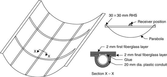
FIGURE 3.18 Fiberglass parabola details.
Tracking mechanisms
A tracking mechanism must be reliable and able to follow the sun with a certain degree of accuracy, return the collector to its original position at the end of the day or during the night, and track during periods of intermittent cloud cover. Additionally, tracking mechanisms are used for the protection of collectors, that is, they turn the collector out of focus to protect it from hazardous environmental and working conditions, such as wind gusts, overheating, and failure of the thermal fluid flow mechanism. The required accuracy of the tracking mechanism depends on the collector acceptance angle. This is described in Section 3.6.3, and the method to determine it experimentally is given in Section 4.3.
Various forms of tracking mechanisms, ranging from complex to very simple, have been proposed. They can be divided into two broad categories: mechanical and electrical–electronic systems. The electronic systems generally exhibit improved reliability and tracking accuracy. These can be further subdivided into:
1. Mechanisms employing motors controlled electronically through sensors, which detect the magnitude of the solar illumination (Kalogirou, 1996).
2. Mechanisms using computer-controlled motors, with feedback control provided from sensors measuring the solar flux on the receiver (Briggs, 1980; Boultinghouse, 1982).
A tracking mechanism developed by the author (Kalogirou, 1996) uses three light-dependent resistors (LDRs), which detect the focus, sun–cloud, and day–night conditions and give instruction to a DC motor through a control system to focus the collector, follow approximately the sun path when cloudy conditions exist, and return the collector to the east during night.
The system, which was designed to operate with the required tracking accuracy, consists of a small direct current motor that rotates the collector via a speed reduction gearbox. A diagram of the system, together with a table showing the functions of the control system, is presented in Figure 3.19. The system employs three sensors, of which A is installed on the east side of the collector shaded by the frame, whereas the other two (B and C) are installed on the collector frame. Sensor A acts as the “focus” sensor, that is, it receives direct sunlight only when the collector is focused. As the sun moves, sensor A becomes shaded and the motor turns “on”. Sensor B is the “cloud” sensor, and cloud cover is assumed when illumination falls below a certain level. Sensor C is the “daylight” sensor. The condition when all three sensors receive sunlight is translated by the control system as daytime with no cloud passing over the sun and the collector in a focused position. The functions shown in the table of Figure 3.19 are followed provided that sensor C is “on”, that is, it is daytime.
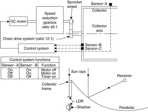
FIGURE 3.19 Tracking mechanism, system diagram.
The sensors used are light-dependent resistors (LDRs). The main disadvantage of LDRs is that they cannot distinguish between direct and diffuse sunlight. However, this can be overcome by adding an adjustable resistor to the system, which can be set for direct sunlight (i.e., a threshold value). This is achieved by setting the adjustable resistor so that for direct sunlight, the appropriate input logic level (i.e., 0) is set.
As mentioned previously, the motor of the system is switched on when any of the three LDRs is shaded. Which sensor is activated depends on the amount of shading determined by the value set on the adjustable resistor, that is, threshold value of radiation required to trigger the relays. Sensor A is always partially shaded. As the shading increases due to the movement of the sun, a value is reached that triggers the forward relay, which switches the motor on to turn the collector and therefore re-exposes sensor A.
The system also accommodates cloud cover, that is, when sensor B is not receiving direct sunlight, determined by the value of another adjustable resistor, a timer is automatically connected to the system and this powers the motor every 2 min for about 7 s. As a result, the collector follows approximately the sun’s path and when the sun reappears the collector is refocused by the function of sensor A.
The system also incorporates two limit switches, the function of which is to stop the motor from going beyond the rotational limits. These are installed on two stops, which restrict the overall rotation of the collector in both directions, east and west. The collector tracks to the west as long as it is daytime. When the sun goes down and sensor C determines that it is night, power is connected to a reverse relay, which changes the motor’s polarity and rotates the collector until its motion is restricted by the east limit switch. If there is no sun during the following morning, the timer is used to follow the sun’s path as under normal cloudy conditions. The tracking system just described, comprising an electric motor and a gearbox, is for small collectors. For large collectors, powerful hydraulic units are required.
The tracking system developed for the EuroTrough collector is based on “virtual” tracking. The traditional sun-tracking unit with sensors that detect the position of the sun has been replaced by a system based on calculation of the sun position using a mathematical algorithm. The unit is implemented in the EuroTrough with a 13-bit optical angular encoder (resolution of 0.8 mrad) mechanically coupled to the rotation axis of the collector. By comparing both sun and collector axes positions by an electronic device, an order is sent to the drive system to induce tracking.
3.2.2 Fresnel collectors
Fresnel collectors have two variations: the Fresnel lens collector (FLC), shown in Figure 3.20(a), and the linear Fresnel reflector (LFR), shown in Figure 3.20(b). The former is made from a plastic material and shaped in the way shown to focus the solar rays to a point receiver, whereas the latter relies on an array of linear mirror strips that concentrate light onto a linear receiver. The LFR collector can be imagined as a broken-up parabolic trough reflector (see Figure 3.20(b)), but unlike parabolic troughs, the individual strips need not be of parabolic shape. The strips can also be mounted on flat ground (field) and concentrate light on a linear fixed receiver mounted on a tower. A representation of an element of an LFR collector field is shown in Figure 3.21. In this case, large absorbers can be constructed and the absorber does not have to move. The greatest advantage of this type of system is that it uses flat or elastically curved reflectors, which are cheaper than parabolic glass reflectors. Additionally, these are mounted close to the ground, thus minimizing structural requirements.
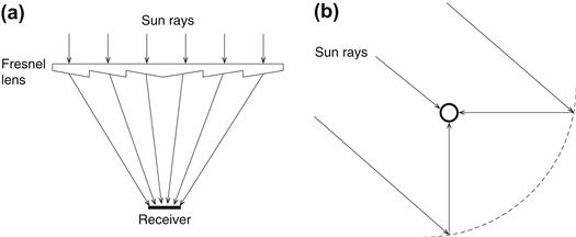
FIGURE 3.20 Fresnel collectors. (a) Fresnel lens collector (FLC). (b) Linear Fresnel-type parabolic trough collector.
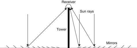
FIGURE 3.21 Schematic diagram of a downward-facing receiver illuminated from an LFR field.
The first to apply this principle was the great solar pioneer Giorgio Francia (1968), who developed both linear and two-axis tracking Fresnel reflector systems at Genoa, Italy, in the 1960s. These systems showed that elevated temperatures could be reached using such systems, but he moved on to two-axis tracking, possibly because advanced selective coatings and secondary optics were not available (Mills, 2001).
In 1979, the FMC Corporation produced a detailed project design study for 10 and 100 MWe LFR power plants for the U.S. Department of Energy (DOE). The larger plant would have used a 1.68 km linear cavity absorber mounted on 61 m height towers. The project, however, was never put into practice, because it ran out of DOE funding (Mills, 2001).
A later effort to produce a tracking LFR was made by the Israeli Paz company in the early 1990s by Feuermann and Gordon (1991). This used efficient secondary CPC-like optics and an evacuated tube absorber.
One difficulty with the LFR technology is that avoidance of shading and blocking between adjacent reflectors leads to increased spacing between reflectors. Blocking can be reduced by increasing the height of the absorber towers, but this increases cost. Compact linear Fresnel reflector (CLFR) technology has been recently developed at Sydney University in Australia. This is, in effect, a second type of solution for the Fresnel reflector field problem that has been overlooked until recently. In this design adjacent linear elements can be interleaved to avoid shading. The classical LFR system has only one receiver and there is no choice about the direction and orientation of a given reflector. However, if it is assumed that the size of the field will be large, as it must be in technology supplying electricity in the megawatt class, it is reasonable to assume that there will be many towers in the system. If they are close enough, then individual reflectors have the option of directing reflected solar radiation to at least two towers. This additional variable in the reflector orientation provides the means for much more densely packed arrays because patterns of alternating reflector orientation can be such that closely packed reflectors can be positioned without shading and blocking. The interleaving of mirrors between two receiving towers is shown in Figure 3.22. The arrangement minimizes beam blocking by adjacent reflectors and allows high reflector densities and low tower heights to be used. Close spacing of reflectors reduces land usage, but in many cases, as in deserts, this is not a serious issue. The avoidance of large reflector spacing and tower heights is also an important cost issue when the cost of ground preparation, array substructure cost, tower structure cost, steam line thermal losses, and steam line cost are considered. If the technology is to be located in an area with limited land availability, such as in urban areas or next to existing power plants, high array ground coverage can lead to maximum system output for a given ground area (Mills, 2001).
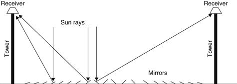
FIGURE 3.22 Schematic diagram showing interleaving of mirrors in a CLFR with reduced shading between mirrors.
A good review of solar energy applications of Fresnel lenses is given by Xie et al. (2011). This includes both imaging and non-imaging systems.
Parabolic dish reflector (PDR)
A parabolic dish reflector (PDR), shown schematically in Figure 3.23(a), is a point-focus collector that tracks the sun in two axes, concentrating solar energy onto a receiver located at the focal point of the dish. The dish structure must fully track the sun to reflect the beam into the thermal receiver. For this purpose, tracking mechanisms similar to the ones described in the previous section are employed in double, so the collector is tracked in two axes. A photograph of a Eurodish collector is shown in Figure 3.23(b).
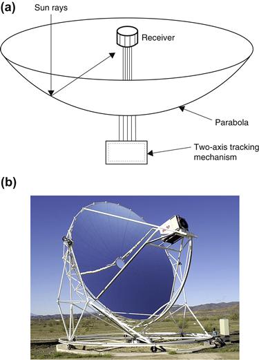
FIGURE 3.23 Parabolic dish collector. (a) Schematic diagram. (b) Photo of a Eurodish collector. From http://www.psa.es/webeng/instalaciones/discos.php.
The receiver absorbs the radiant solar energy, converting it into thermal energy in a circulating fluid. The thermal energy can then be either converted into electricity using an engine–generator coupled directly to the receiver or transported through pipes to a central power conversion system. Parabolic dish systems can achieve temperatures in excess of 1500 °C. Because the receivers are distributed throughout a collector field, like parabolic troughs, parabolic dishes are often called distributed receiver systems. Parabolic dishes have several important advantages (De Laquil et al., 1993):
1. Because they are always pointing at the sun, they are the most efficient of all collector systems.
2. They typically have concentration ratios in the range of 600–2000 and thus are highly efficient at thermal energy absorption and power conversion systems.
3. They are modular collector and receiver units that can function either independently or as part of a larger system of dishes.
The main use of this type of concentrator is for parabolic dish engines. A parabolic dish engine system is an electric generator that uses sunlight instead of crude oil or coal to produce electricity. The major parts of a system are the solar dish concentrator and the power conversion unit. More details on this system are given in Chapter 10.
Parabolic dish systems that generate electricity from a central power converter collect the absorbed sunlight from individual receivers and deliver it via a heat transfer fluid to the power conversion systems. The need to circulate heat transfer fluid throughout the collector field raises design issues such as piping layout, pumping requirements, and thermal losses.
3.2.4 Heliostat field collector (HFC)
For extremely high inputs of radiant energy, a multiplicity of flat mirrors, or heliostats, using altazimuth mounts can be used to reflect their incident direct solar radiation onto a common target, as shown in Figure 3.24. This is called the heliostat field or central receiver collector. By using slightly concave mirror segments on the heliostats, large amounts of thermal energy can be directed into the cavity of a steam generator to produce steam at high temperature and pressure.
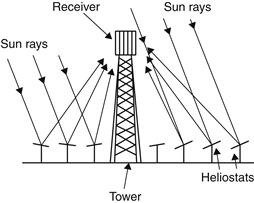
FIGURE 3.24 Schematic of central receiver system.
The concentrated heat energy absorbed by the receiver is transferred to a circulating fluid that can be stored and later used to produce power. Central receivers have several advantages (De Laquil et al., 1993):
1. They collect solar energy optically and transfer it to a single receiver, thus minimizing thermal energy transport requirements.
2. They typically achieve concentration ratios of 300–1500 and so are highly efficient, both in collecting energy and in converting it to electricity.
3. They can conveniently store thermal energy.
4. They are quite large (generally more than 10 MW) and thus benefit from economies of scale.
Each heliostat at a central receiver facility has from 50 to 150 m2 of reflective surface, with four mirrors installed on a common pillar for economy, as shown in Figure 3.25. The heliostats collect and concentrate sunlight onto the receiver, which absorbs the concentrated sunlight, transferring its energy to a heat transfer fluid. The heat transport system, which consists primarily of pipes, pumps, and valves, directs the transfer fluid in a closed loop among the receiver, storage, and power conversion systems. A thermal storage system typically stores the collected energy as sensible heat for later delivery to the power conversion system. The storage system also decouples the collection of solar energy from its conversion to electricity. The power conversion system consists of a steam generator, turbine generator, and support equipment, which convert the thermal energy into electricity and supply it to the utility grid.
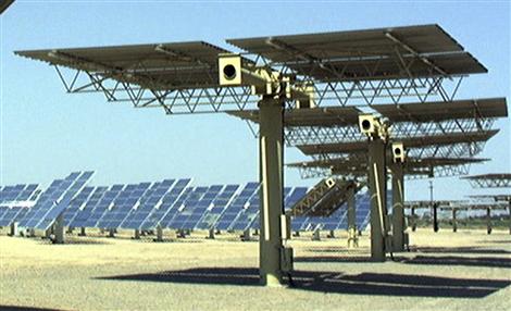
FIGURE 3.25 Detail of a heliostat.
In this case incident sunrays are reflected by large tracking mirrored collectors, which concentrate the energy flux toward radiative–convective heat exchangers, where energy is transferred to a working thermal fluid. After energy collection by the solar system, the conversion of thermal energy to electricity has many similarities with the conventional fossil-fueled thermal power plants (Romero et al., 2002).
The collector and receiver systems come in three general configurations. In the first, heliostats completely surround the receiver tower, and the receiver, which is cylindrical, has an exterior heat transfer surface. In the second, the heliostats are located north of the receiver tower (in the Northern Hemisphere), and the receiver has an enclosed heat transfer surface. In the third, the heliostats are located north of the receiver tower, and the receiver, which is a vertical plane, has a north-facing heat transfer surface. More details of these plants are given in
Leave a Reply