
A schematic diagram of a typical air-heating flat-plate solar collector is shown in Figure 3.33. The air passage is a narrow duct with the surface of the absorber plate serving as the top cover. The thermal analysis presented so far applies equally well here, except for the fin efficiency and the bond resistance.
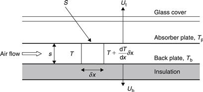
FIGURE 3.33 Schematic diagram of an air-heating collector.
An energy balance on the absorber plate of area (1 × δx) gives:
![]() (3.71)
(3.71)
hc,p–a = convection heat transfer coefficient from absorber plate to air (W/m2 K).
hr,p–b = radiation heat transfer coefficient from absorber plate to back plate, which can be obtained from Eq. (2.73), (W/m2 K).
An energy balance of the air stream volume (s × 1 × δx) gives:
![]() (3.72)
(3.72)
hc,b–a = convection heat transfer coefficient from the back plate to air (W/m2 K).
An energy balance on the back plate area (1 × δx) gives:
![]() (3.73)
(3.73)
As Ub is much smaller than Ut, UL ≈ Ut. Therefore, neglecting Ub and solving Eq. (3.73) for Tb gives:
![]() (3.74)
(3.74)
Substituting Eq. (3.74) into Eq. (3.71) gives:
![]() (3.75)
(3.75)
where
![]() (3.76)
(3.76)
Substituting Eq. (3.74) into Eq. (3.72) gives:
![]() (3.77)
(3.77)
Finally, combining Eqs (3.75) and (3.77) gives:
![]() (3.78)
(3.78)
where F′ = collector efficiency factor for air collectors, given by:
![]() (3.79)
(3.79)
The initial conditions of Eq. (3.78) are T = Ti at x = 0. Therefore, the complete solution of Eq. (3.78) is:
![]() (3.80)
(3.80)
This equation gives the temperature distribution of air in the duct. The temperature of the air at the outlet for the collector is obtained from Eq. (3.80), using x = L and considering Ac = WL. Therefore,
![]() (3.81)
(3.81)
The energy gain by the air stream is then given by:
![]() (3.82)
(3.82)
Using the equation for the heat removal factor given by Eq. (3.58), Eq. (3.82) gives:
![]() (3.83)
(3.83)
Since S = (τα)Gt, Eq. (3.83) is essentially the same as Eq. (3.60).
EXAMPLE 3.6
Estimate the outlet air temperature and efficiency of the collector shown in Figure 3.33 for the following collector specifications:
Depth of air channel, s = 15 mm.
Total insolation, Gt = 890 W/m2
Ambient temperature, Ta = 15 °C = 288 K.
Heat loss coefficient, UL = 6.5 W/m2 K.
Emissivity of absorber plate, εp = 0.92.
Emissivity of back plate, εb = 0.92.
Mass flow rate of air = 0.06 kg/s.
Inlet air temperature, Ti = 50 °C = 323 K.
Solution
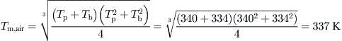
Here we need to start by assuming values for Tp and Tb. To save time, the correct values are selected; but in an actual situation, the solution needs to be found by iteration. The values assumed are Tp = 340 K and Tb = 334 K (these need to be within 10 K). From these two temperatures, the mean air temperature can be determined from:
from which
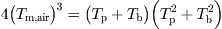
The radiation heat transfer coefficient from the absorber to the back plate is given by:

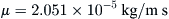
From Tm, air, the following properties of air can be obtained from Appendix 5:
From fluid mechanics the hydraulic diameter of the air channel is given by:

The Reynolds number is given by:

Therefore, the flow is turbulent, for which the following equation applies: Nu = 0.0158(Re)0.8. Since Nu = (hcD)/k, the convection heat transfer coefficient is given by:

From Eq. (3.76),

From Eq. (3.79),
The absorbed solar radiation is:

From Eq. (3.81),

Therefore, the average air temperature is ½(351 + 323) = 337 K, which is the same as the value assumed before. If there is a difference in the two mean values, an iteration is required. This kind of problem requires just one iteration to find the correct solution by using the assumed values, which give the new mean temperature.
From Eq. (3.58),

From Eq. (3.83),

Finally, the collector efficiency is:
Another case of air collector is to have airflow between the absorbing plate and the glass cover. This is shown graphically in Figure 3.34 together with the thermal resistance network.
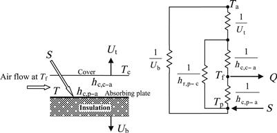
FIGURE 3.34 Solar air heater and its thermal resistance network.
By following an energy balance of the cover, plate and fluid flowing through the collector the following set of equations can be obtained:
![]() (3.84a)
(3.84a)
![]() (3.84c)
(3.84c)
In these equations hr,p–c represent the radiation heat transfer coefficient from absorbing plate to cover and is given by Eq. (2.73) and
hc,c–a = convection heat transfer coefficient from cover to air (W/m2 K)
hc,p–a = convection heat transfer coefficient from absorbing plate to air (W/m2 K)
By performing some long algebraic manipulations to eliminate Tp and Tc the rate of useful energy can be obtained from:
![]() (3.85)
(3.85)
where
![]() (3.86a)
(3.86a)

Leave a Reply